7.3 Connecting Peripheral Devices
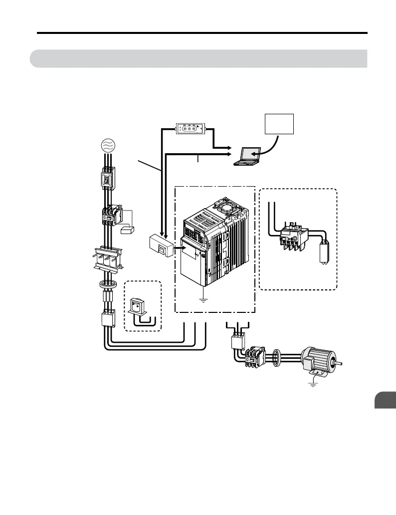
Figure 7.1 illustrates connections between the drive, motor, and various peripheral devices.
Refer to peripheral device option manual for detailed installation instructions.
+2+1
Power
supply
Magnetic
contactor
(MC)
Line
breaker
(MCCB)
or
Leakage
breaker
AC reactor
Zero phase
reactor
Input side
noise filter
DC reactor
Surge
protector
Fuse
Option
Interface
unit
U/T1 V/T2 W/T3R/L1 S/L2 T/L3
Drive
Ground
Output side
noise filter
Zero phase
reactor
Ground
Motor
Backup
Contactor
B1 B2
DriveWizardPlus
Magnetic contactor
(MC)
Braking
resistor
unit
Copy
Verify
Read
LOCK
YASKAWA
JVOP-181
USB Copy Unit
COM ERR
PC
Engineering software tools
Dedicated Cable
(RJ-45/D-sub adapter)
(30 cm)
RJ-45 cable
(1 m)
USB Copy Unit
(RJ-45/USB adapter)
USB cable
<2>
<1>
Figure 7.1 Connecting Peripheral Devices
<1> NOTICE: Do not connect the LAN port on a PC and the comm. port of the RS-232C
Interface Option Unit (SI-232/J and SI-232/JC). Failure to comply may damage the option
unit and the PC. Use the USB Copy Unit with an RJ-45 cable and USB cable as shown in
Figure 7.1 to connect the drive to a PC.
7.3 Connecting Peripheral Devices
YASKAWA ELECTRIC TOEP C710606 25D YASKAWA AC Drive J1000 Installation & Start-Up Manual
189
7
Peripheral Devices &
Options

 Loading...


