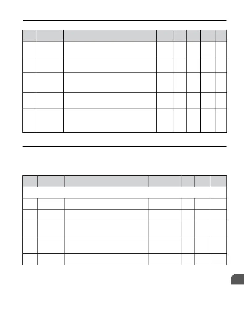
No. Name Description Range Def. Mode
Addr.
Hex
Pg.
o4-03
Cooling Fan
Operation
Time Setting
Sets the value of the fan operation time in units of 10
h.
0 to
9999
0 O 50E –
o4-05
Capacitor
Maintenance
Setting
Sets the value of the capacitor maintenance time
monitor U4-05.
0 to 150 0% O 51D –
o4-07
DC Bus Pre-
Charge Relay
Maintenance
Setting
Sets the value of the Soft Charge Bypass Relay
Maintenance monitor U4-06.
0 to 150 0% O 523 –
o4-09
IGBT
Maintenance
Setting
Sets the value of the IGBT Maintenance monitor
U4-07.
0 to 150 0% O 525 –
o4-11 U2
Initialization
0: U2-oo monitor data are not reset when the drive
is initialized using A1-03.
1: U2-oo monitor data are reset when the drive is
initialized using A1-03. (The value of o4-11 is
automatically returned to 0.)
0, 1 0 O 510 –
<1> Parameter can be changed during run.
u
U: Monitors
Monitor parameters allow the user to view drive status, fault information, and other
information about drive operation.
No. Name Description
Analog Output
Level
Unit Mode
Addr.
Hex
U1: Operation Status Monitors
Use U1 monitors to display the operation status of the drive.
U1-01
Frequency
Reference
Monitors the frequency reference
10 V: Max
frequency
0.01
Hz
O 40
U1-02
Output
Frequency
Displays the output frequency. Display units are
determined by o1-03.
10 V: Max
frequency
0.01
Hz
O 41
U1-03
Output
Current
Displays the output current.
10 V: Drive rated
current
0.01
A
<1>
O 42
U1-06
Output
Voltage
Reference
Displays the output voltage.
10 V: 200 Vrms
(400 Vrms)
0.1 V O 45
U1-07
DC Bus
Voltage
Displays the DC bus voltage.
10 V: 400 V (800
V)
1 V O
46
B.2 Parameter Table
YASKAWA ELECTRIC TOEP C710606 25D YASKAWA AC Drive J1000 Installation & Start-Up Manual
243
B
Parameter List

 Loading...


