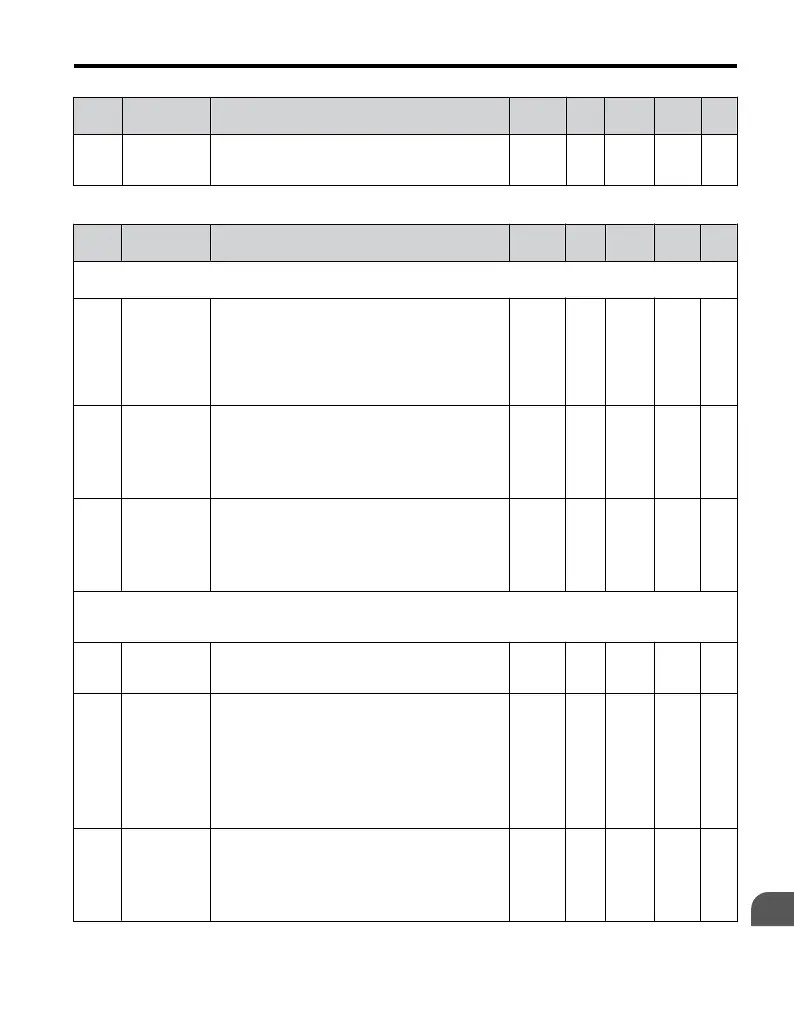
No. Name Description Range Def. Mode
Addr.
Hex
Pg.
H3-13
Analog Input
Filter Time
Constant
Sets the primary delay filter time constant for
terminal A1 or potentiometer (optional). Used for
noise filtering.
0.00 to
2.00
0.03
s
O 41B –
<1> Parameter can be changed during run.
No. Name Description Range Def. Mode
Addr.
Hex
Pg.
H4: Multi-Function Analog Output AM
Use H4 parameters to configure the multi-function analog output terminal AM.
H4-01
Multi-
Function
Analog
Output
Terminal
AM
Selects the data to be output through multi-function
analog output terminal AM.
Set the desired monitor parameter to the digits
available in Uo-oo. For example, enter “103” for
U1-03.
When using this terminal in through mode or when
not using it at all, set “000” or “031”.
000 to
999
102 O 41D 111
H4-02
<1>
Multi-
Function
Analog
Output
Terminal AM
Gain
Sets terminal AM output level when selected
monitor is at 100%.
Maximum output voltage is 10 V.
-999.9
to 999.9
100.0
%
S 41E 111
H4-03
<1>
Multi-
Function
Analog
Output
Terminal AM
Bias
Sets terminal AM output level when selected
monitor is at 0%.
-999.9
to 999.9
0.0% O 41F 111
H5: MEMOBUS/Modbus Communications
Use H5 Parameters to connect the drive to a MEMOBUS/Modbus network.
The settings for MEMOBUS/Modbus communications become effective when the drive is restarted.
H5-01
<2>
Drive Slave
Address
Selects drive slave number (address) for
MEMOBUS/Modbus communication. Cycle power
for the setting to take effect.
0 to FF 1F O 425 –
H5-02
Comm. Speed
Selection
Selects the baud rate for MEMOBUS/Modbus
communication. Cycle power for the setting to take
effect.
0 : 1200 bps
1 : 2400 bps
2 : 4800 bps
3 : 9600 bps
4 : 19200 bps
5 : 38400 bps
0 to 5 3 O 426 –
H5-03
Comm. Parity
Selection
Selects the communication parity for MEMOBUS/
Modbus
communication. Cycle power for the setting
to take effect.
0: No parity
1: Even parity
2: Odd parity
0 to 2
0 O 427 –
B.2 Parameter Table
YASKAWA ELECTRIC TOEP C710606 25D YASKAWA AC Drive J1000 Installation & Start-Up Manual
235
B
Parameter List

 Loading...


