Drive
A1
0 to 10 V
AC
I V
Main frequency
(voltage or current input)
Analog common
DIP switch S1
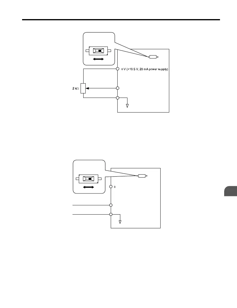
Figure 4.7 Voltage Input for the Frequency Reference
Current Input
When entering the frequency reference using an analog input signal, set parameter H3-01 to
“2” if 4 to 20 mA input is used. When using 0 to 20 mA input, set H3-01 to “3”. Set DIP
Switch S1 for current input (position “I”).
V (+10.5 V, 20 mA power supply)
0 or 4 to 20 mA input
DIP switch S1
I V
Drive
A1
Main Frequency
(current input)
AC
Analog common
Figure 4.8 Current Input for the Frequency Reference
4.5 Basic Operation
YASKAWA ELECTRIC TOEP C710606 25D YASKAWA AC Drive J1000 Installation & Start-Up Manual
95
4
Start-Up Programming
& Operation

 Loading...


