2.1 Main Circuit Wiring
13
■ Power ON Sequence Design
Keep the following in mind when designing a Power ON Sequence.
• Design the power feed sequence so that the power goes OFF if a “Servo Alarm” is
output. See “Figure A Main Circuit Wiring Example” on page 12.
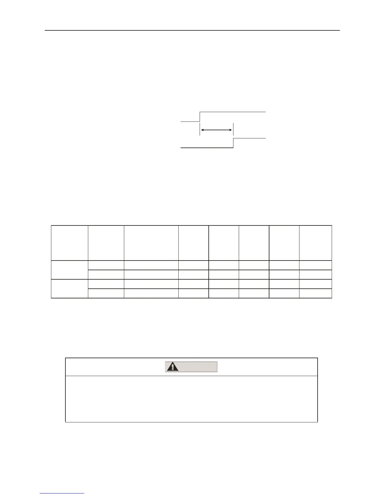
• Hold down the power ON button for at least two seconds. The digital torque
amplifier will output a “Servo Alarm” signal for at most two seconds at power ON.
This is necessary for digital torque amplifier initial setting.
■ Power Line Size and Peripheral Devices
See the Sigma II Series Servo System User's Manual: Servo Selection and Data Sheet
edition. (Document Number: YEA-SIA-S800-32.2x)
■ Digital Torque Amplifier Power Loss
The digital torque amplifier power loss at continuous output is shown in Table 2.2 below.
Note: The regen resistor power loss is the allowable power loss. Take the following measures if this
value is exceeded. Remove the lead wire of the digital torque amplifier's integrated regen
resistor and install an external regen resistor. Furthermore, the external regen resistor is an
option. For details on regen resistors, see “
4.5 Regenerative Resistor Selection”.
■ Main Circuit Terminal Block Wiring Method
Observe the following cautionary items when wiring.
Servo amplifiers with capacities of 1.5kW or less consist of a connector-type terminal
block for the main circuit. Wire the terminal block by the following procedure.
Table 2.2: Digital Torque Amplifier Power Loss at Continuous Output
Main
Circuit
Max.
Applied
Motor
Capacity
Digital Torque
Amplifier Model
Output
Current
(actual)
A
Main
Circuit
Power
Loss W
Regen
Resistor
Power
Loss W
Control
Circuit
Power
Loss W
Total
Power
Loss W
Single-phase
200V
0.10 SGDG–01GT 0.91 6.7 – 13 19.7
0.40 SGDG–04GT 2.8 20 – 13 33
3-phase
200V
1.0 SGDG–10GT 7.6 55 12 15 82
1.5 SGDG–15GT 11.6 123 14 15 152
• Perform wiring after removing the terminal block from the digital torque amplifier unit.
• Insert one wire into each power line insertion aperture in the terminal block.
• When inserting the power lines, be sure that they do not short against the surrounding material due to
exposed wire cores.
• Power lines that have been mistakenly pulled out by excessive force should be re-stripped then connected.
2.0s Max.
Power
ervo Alarm (ALM) Output Signal
CAUTION