4.1 Torque/Force Control
41
4. Description of Functions
4.1 Torque/Force Control
This is the torque/force control-dedicated mode.
This control mode inputs the torque/force reference from CMD-IN (CN1-3 & CN1-4).
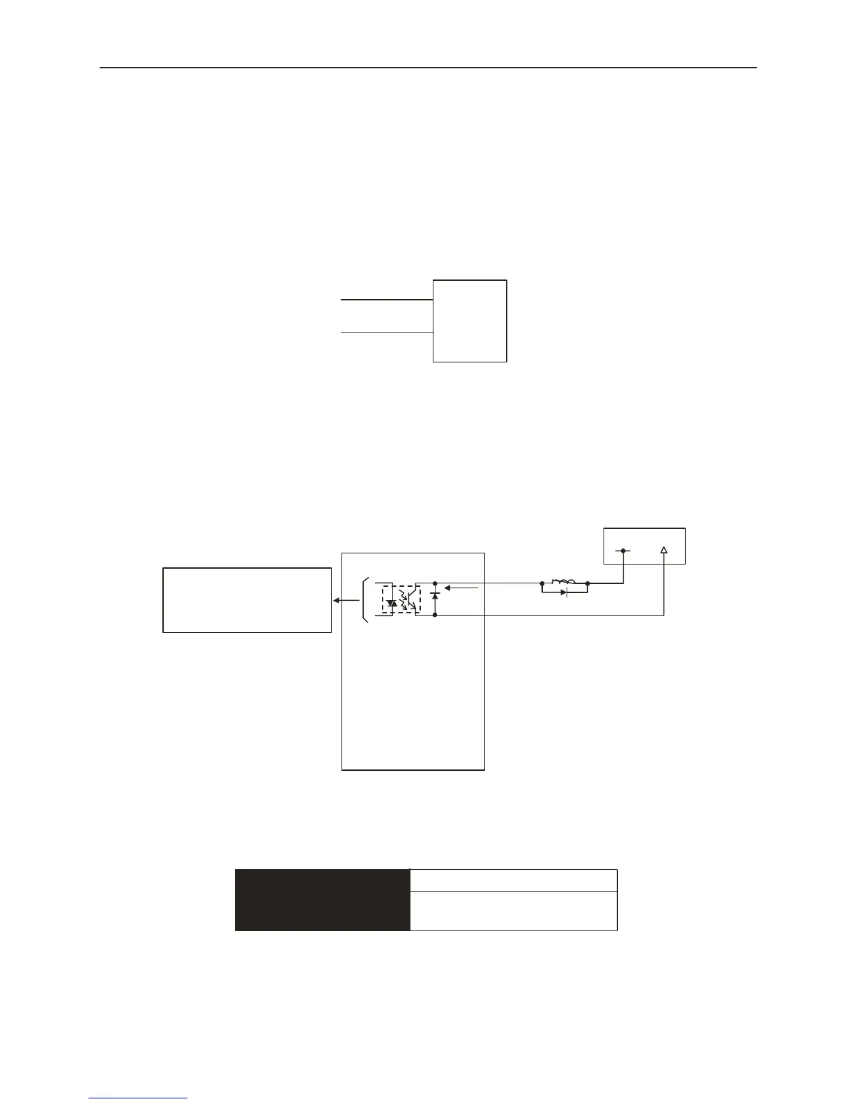
4.2 Protection Sequence Design
This section describes the methods for integrating a protective sequence for safety purposes
using I/O signals from the digital torque amplifier.
Servo Alarm Output
The basic method for continuing alarm-related “output signals” is shown below.
Prepare an external 24V usage power source. No 24V power source is integrated in the digital
torque amplifier. The photocoupler output signal is handled as follows:
The output is “ON” when the digital torque amplifier detects an error.
Output → ALM+ CN1-34
Servo Alarm Output
Output → ALM- CN1-35
Signal ground for servo alarm
output
CMD-IN
Amplifier
CN1-3
SG
CN1-4
CMD-IN
SG
Digita l Torque A m plifier
CN1-34
CN1-35
ALM+
ALM-
24V P ow er
+24V
0V
Photocoupler
Photocoupler Output per
Output
Max. Usage voltage: DC30V
Max. Usage Current: :DC50mA
MAX 50mA
Digital Torque Amplifier