2.2 Input Signals
17
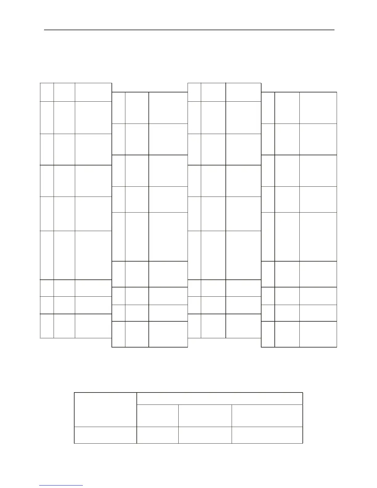
■ Connector (CN1) Terminal Array List
The CN1 terminal array and its specifications are shown below.
CN1 Terminal Layout
Note 1 Do not use empty terminals for relays.
Note 2 Connect the I/O signal cable shield wire to the connector shell. This is connected to the
frame ground on the digital torque amplifier side connector.
■ CN1 Specifications
1--- --- 19GND GND
20 PAO
Encoder
Divided
Output A
phase+
3
CMD
-IN
Torque/
Force
Reference
Input
2 GND GND
21 *PAO
Encoder
Divided
Output A
phase-
4 GND GND 22 PBO
Encoder
Divided
Output B
phase+
5 --- --- 23 *PB0
Encoder
Divided
Output B
phase-
6 GND GND 24 PCO
Encoder
Divided
Output C
phase+
7
RUN
+
RUN Signal
Output
25 *PCO
Encoder
Divided
Output C
phase-
8 --- --- 26 /S-ON5
Servo ON
Input
9 --- --- 27
DB
OFF5
DB OFF
Signal Input
10 RUN -
RUN Signal
Output
28
SPD-
MON
Speed
Monitor
1V/1000
RPM
29
Torque
Mon
Torque
Monitor
5V/Max.
Torque
11 --- ---
12 --- --- 30 --- ---
13 +24V
External
Power Input
31 --- ---
14 /S-ON
Servo ON
Signal Input
32 --- ---
15
DB
OFF
DB OFF
Signal Input
33 GND GND
16 --- --- 34
ALM
+
Servo Alarm
Output
17 --- --- 35 ALM -
Servo
Alarm
Output
18 --- --- 36 --- ---
Specification for
Connector Used in
Digital Torque
Amplifier
Applied Receptacle Model
Soldering
Type
Case Manufacturer Name
10236-52A2JL-type
Right Angle 36P
10136-3000VE 10336-52A0-008 Sumitomo 3M, Inc.