Appendix A: Host Controller Connection Examples
60
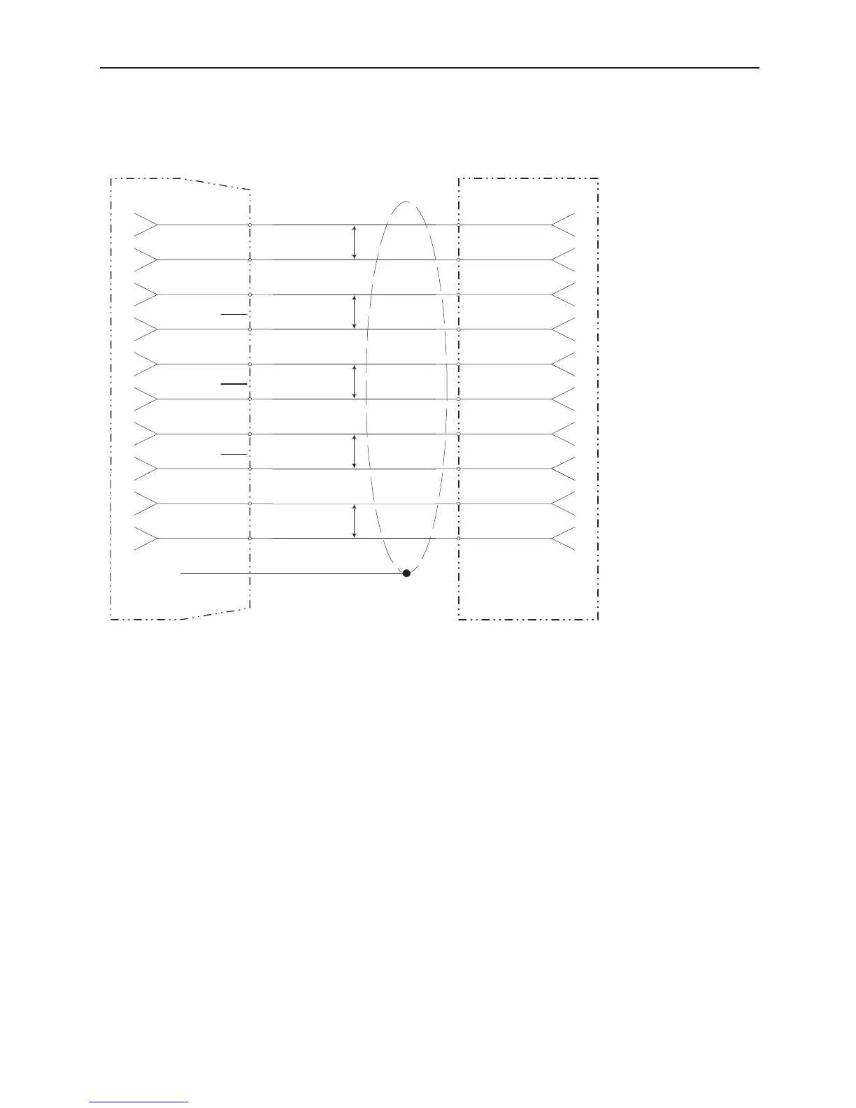
A.4 Connecting the Acroloop ACR-8010
SGDG, CN1
3
CMD-IN
4
GND
20
PAO
21
PAO
22
PBO
23
PBO
24
PCO
25
PCO
26
SV ON5
ASIG-x
AGND-x
P*
OUT-y
CHAn
CHAn'
CHBn
CHBn'
MRKn'
CASE
P*
P*
P*
MRKn
33
GND
AGND
P*
P* = Twisted Pair
n = Axis Designation, 0, 1, 2...
x = Analog output number
y = Digital output number
LEGEND - Acroloop (ACR-8010), Minimum Servo Interface
Encoder type is Differential Line Driver (+5 Volt Outputs) so Pullups should be removed
Encoders 0-3 are on P1A connector
Encoders 4-7 are on P1B connector
ASIG-0 and AGND-0 through ASIG-7 and GND-7 are on P2 connector
AGND is on P2 connector
OUT-32 through OUT-63 are on P3 connector
Torque Reference should b
mapped to one of these
analog outputs
Servo on should be
mapped to one of these
digital outputs