2.2 Input Signals
20
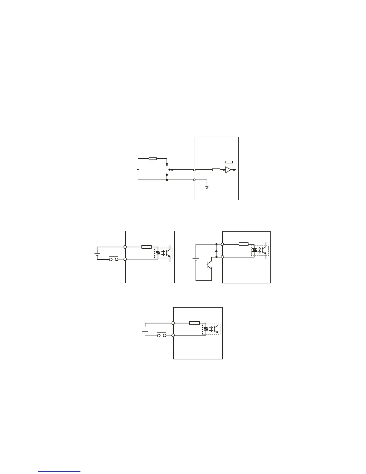
■ Interface Circuit
An example is given below of connection of the digital torque amplifier I/O signals to an
upper level device.
■ Command Input Circuit and Interface
Analog Input Circuit
The analog signal is the torque reference signal. The input impedance is as follows.
• Command Input (CMD-IN): Approx. 14kΩ
The maximum allowable voltage for the input signal is
±12V
• 10V= Peak Motor Torque
■ Sequence Input Circuit and Interface
This is connected by a relay or open collector transistor circuit. Select a low current type
when connecting by relay. If low current relay is not used, this may cause a connection
fault.
12V
1.8kΩ
(1/2W)
or more
25HP-10B
2kΩ
3
1
2
1000:1
0V
SG
Approx.14kΩ
Amplifier
CMD-IN
50mA or more
3.3kΩ
+24VIN
/S-ONetc.
Amplifier
DC24V
50mA or more
3.3kΩ
+24VIN
/S-ON etc.
Amplifier
DC24V
3.3k Ω
+24VIN
/S-ON etc.
Amplifier
50mAor more
DC
24V