2.1 Main Circuit Wiring
14
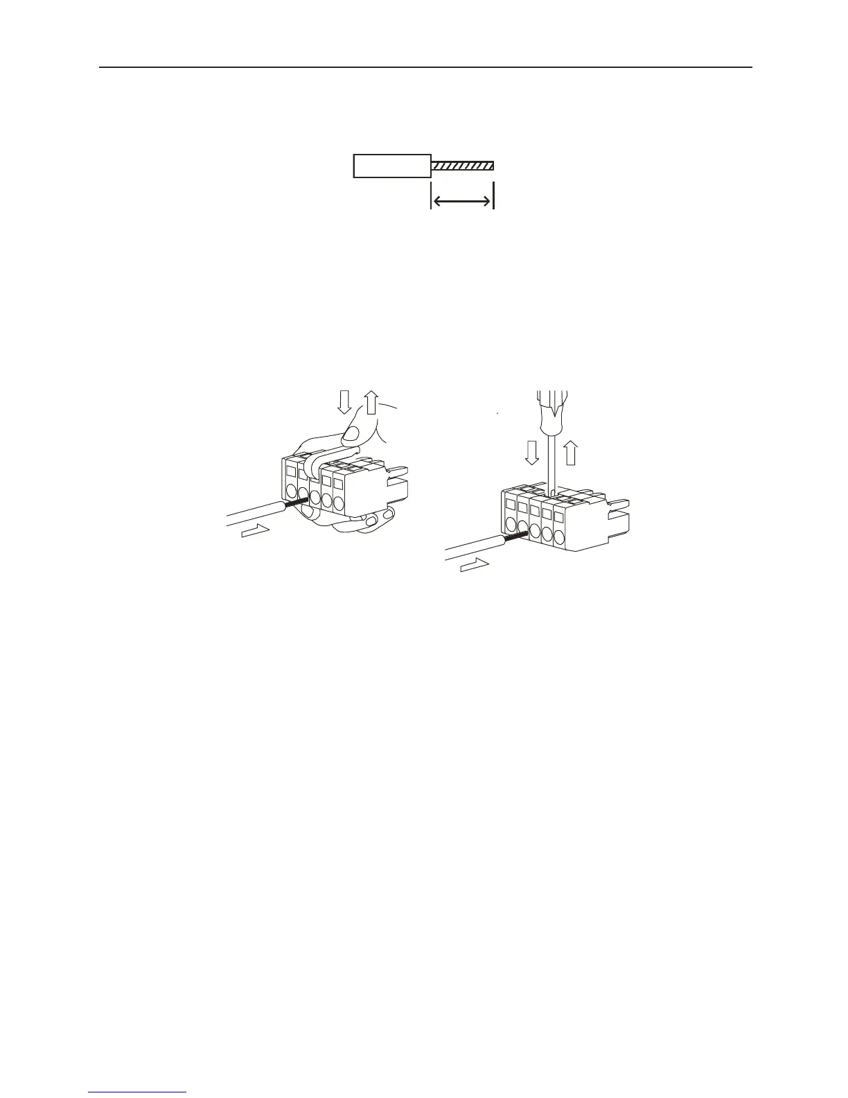
Connection Method
1. Strip the insulation of the power lines used.
2. Open the terminal block wiring insertion area with a tool. There are two opening
methods as shown in figures A and B.
• Figure A shows opening by prying with an accessory lever.
• Figure B shows opening by forcibly pressing the driver insertion aperture with
either a flathead screwdriver head width 3.0~3.5mm (.118~.138 in.) or a 210-120J-
type driver from Wago, Inc. The work can be done using either of the methods in
Figure A: or Figure B:.
3. Insert the core of the power line into the opening. Release the lever or the pressure on
the driver after insertion.
■ Power Terminal Processing
Strip the insulation on the power line. The useable line sizes are as follows:
• Solid Conductor.. φ0.5~φ1.6mm
• Stranded Conductor ..AWG28~AWG12
8
~
9mm
(.315~.35 in
Figure A:
Figure B: