4.2 Protection Sequence Design
42
Be sure to configure the external circuit so that the main power to the digital torque amplifier
goes OFF at alarm output.
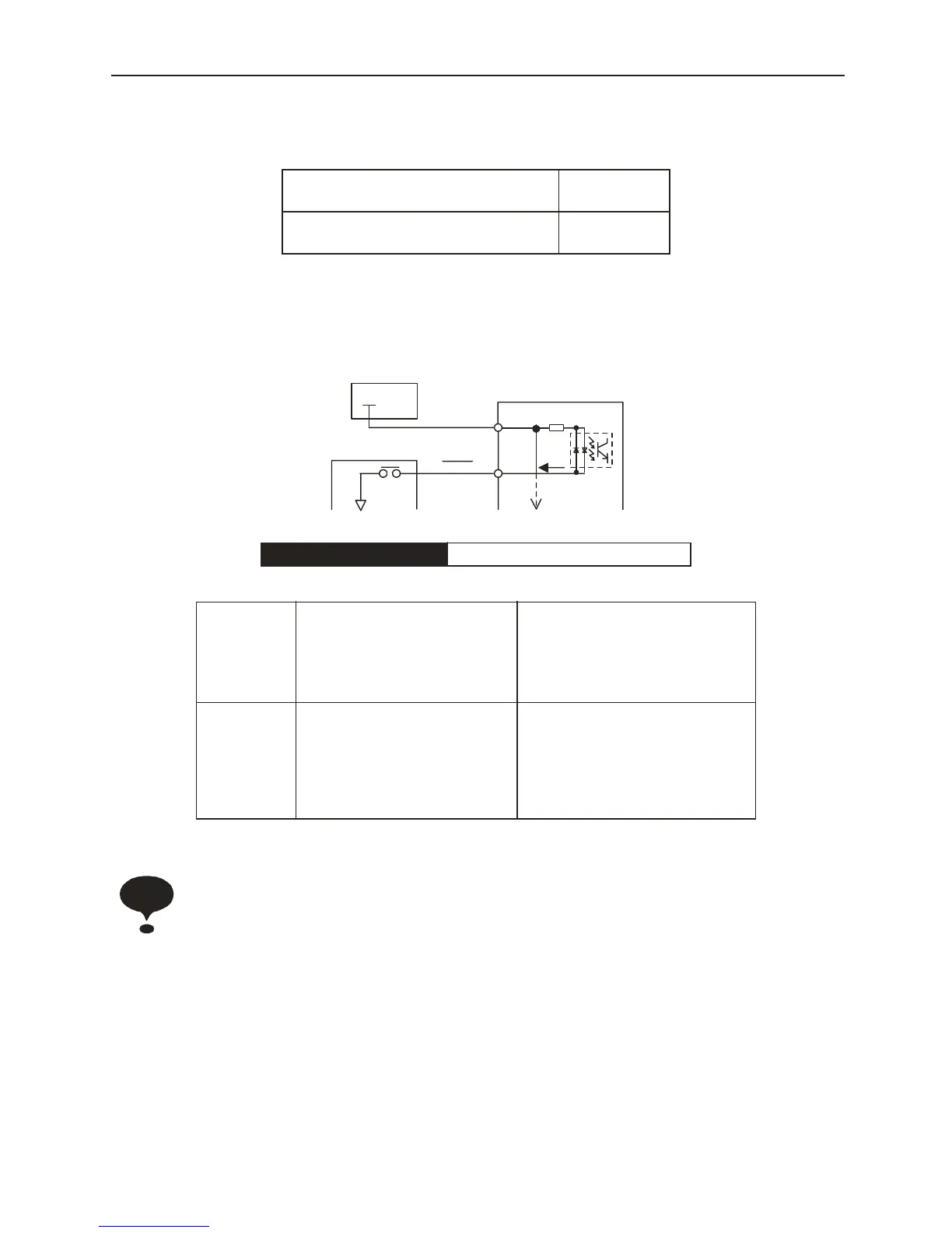
■ Servo ON Input
Serial Input Signal: The basic connection method and for Servo ON (/S-ON) is displayed
below. This is used to forcibly stop the servomotor in a “non-powered” state.
Switches the motor between a powered and a non-powered state.
Do not start/stop the motor by using the (/S-ON) signal. Always start/stop the motor with an
input command.
ON State
CN1–34, 35 is “closed”,
CN1–34 is level “Low”
Normal State
OFF State
CN1–34, 35 is “open”,
CN1–34 is level “High”
Alarm State
→ Input/S-ON CN1-14 Servo ON
When ON
CN1-14 is
“L” level
Sends power to the motor. This is
the normal RUN state. (this is called
the 4state)
Servo ON
Motor “Powered”
State
The motor runs
according to the
input signals
When OFF
CN1-14 is
“H” level
Sets the motor to a “non-powered”
state. Operation is not possible (this
is the Servo OFF state). Do not
perform Servo OFF while the motor
is running except during an
emergency stop.
Servo OFF
Motor Non-Powered
State
Operation is not
possible
24V
Power
+24V
+24VIN
Amplifier
CN1-13 3.3kΩ
Photocouple
Upper-Level
Device
S-ON
CN1-14
5mA
0
V
Important