2.2 Input Signals
18
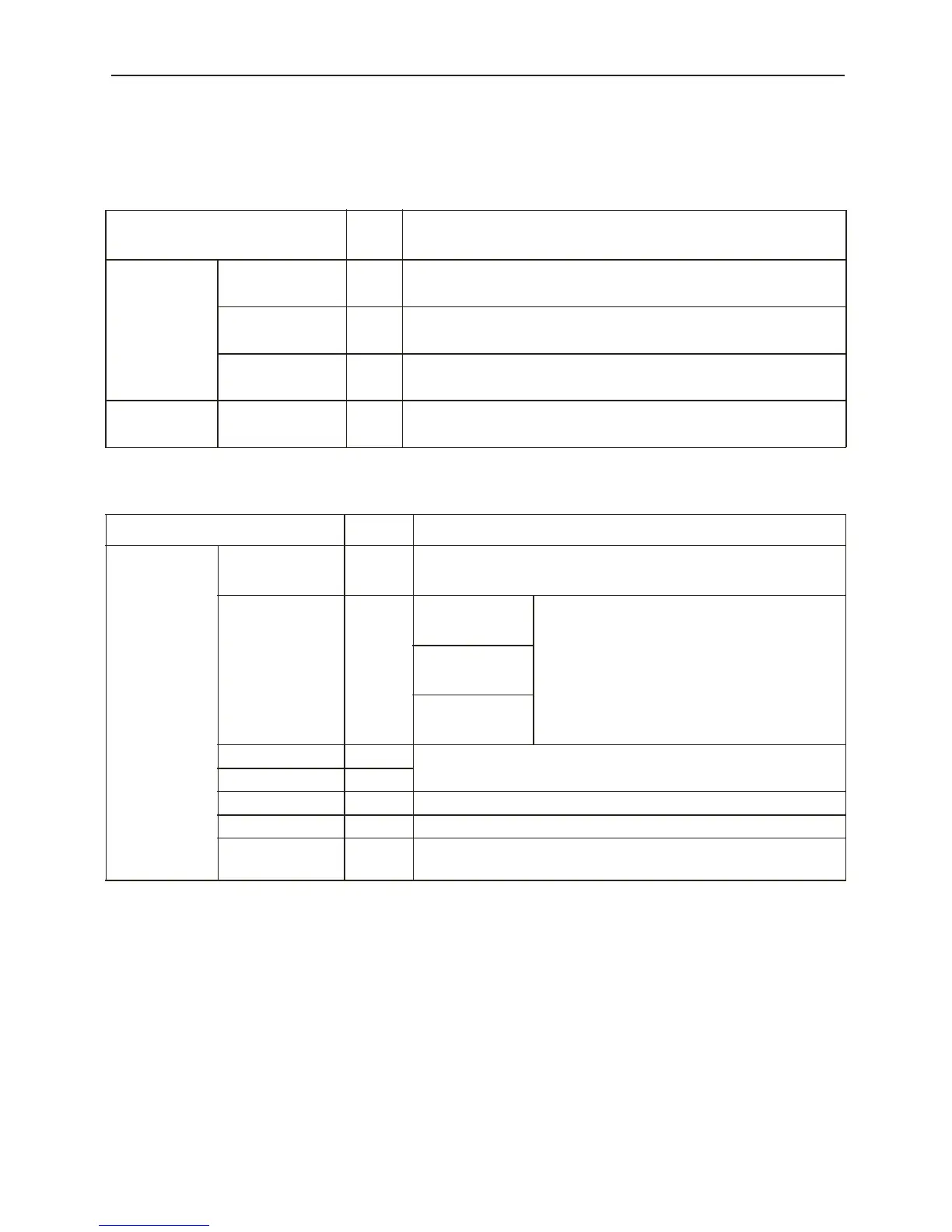
■ I/O Signal Names and Their Functions
The names and functions of the digital torque amplifier I/O signals are shown below.
Input Signals
Signal Name
Pin
No.
Function
Common
/S-ON
14
26
Servo ON
• The inverter output is enabled to provide power to the motor.
DB - OFF
15
DB Release
• A free run state has resulted by releasing the DB.
+24VIN
13
Sequence signal control power input
• +24V power supply provided by customer.
Torque
CMD-IN
3
Torque/Force Reference Input
• -10~+10VDC 10V= Peak Motor Torque
Output Signals
Signal Name Pin No. Function
Common
ALM+
34
Servo Alarm
: Turns OFF due to error detection.
ALM -
35
PAO 20
A-phase Signal
2-phase pulse (A-phase, B-phase)
Conversion Encoder Output Signal
and origin pulse (C-phase) signal
*PAO
21
PBO
22
B-phase Signal
*PBO 23
PCO
24
C-phase Signal
*PCO
25
RUN+
7
Base Block Release Signal
: Output during base block release
RUN - 10
SPD-MON 28 Speed Monitor (1V/1000rpm), Linear Scale 1V/1000mm/sec
TORQUE-MON 29 5V/Max Torque
FG Shell
The frame ground in connected upon connection of the I/O signal cable
shield wire to the connector shell.