2.8 Communications with an OMRON PLC (FINS Communications Service)
Using the MSG-SNDE Function with the MP3000 as the Master
2-212
I/O Memory Data Areas and Corresponding Registers in the
MP3000
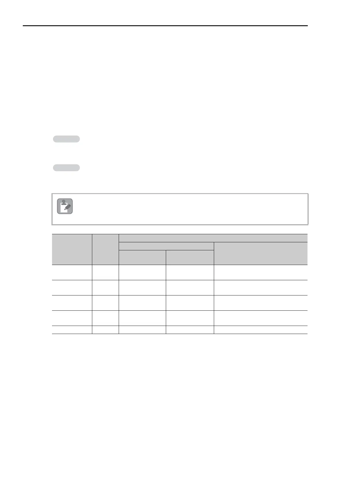
The following table shows the relationship between registers in the MP3000 and the I/O memory data
areas.
A read or write command is automatically generated by specifying the address in the MP3000 that corre-
sponds to the I/O memory to be read from or written to in the OMRON PLC.
Set PARAM14 and PARAM15 of the MSG-SNDE function to the register address in the MP3000 that cor-
responds to the address to read from or write to in the OMRON CPU Unit. Select whether to read or write
by setting the function code in parameter PARAM12 for the MSG-SNDE function.
Note: Word: Specify word addresses.
Writing Data into D10000
Set PARAM14 and PARAM15 to the MW10000 register in the MP3000 that corresponds to
D10000, and set PARAM12 to 0B or 10 hex.
Reading Data from W511
Set PARAM14 and PARAM15 to the MB025590 register in the MP3000 that corresponds to
W511, and set PARAM12 to 01 hex.
To access a relay, specify a bit address in PARAM14 and PARAM15.
Data Area
Name
Data
Type
Data Range
OMRON CPU Unit
MP3000
Addresses
I/O Memory
Addresses
CIO Area Word 000000 to 002047 000000 to 07FF00
Word notation: MW00000 to MW02047
Bit notation: MB000000 to MB02047F
Work Area Word
W00000 to
W00511
00000 to 01FF00
Word notation: MW02048 to MW02559
Bit notation: MB020480 to MB02559F
Holding Area Word H00000 to H00511 00000 to 01FF00
Word notation: MW02560 to MW03071
Bit notation: MB025600 to MB03071F
Auxiliary Area Word A00000 to A00959 00000 to 03BF00
Word notation: MW03072 to MW04031
Bit notation: MB030720 to MB04031F
DM Area Word D00000 to D32767 00000 to 7FFF00 MW00000 to MW32767

 Loading...


