2.16 Details on Protocols
Extended MEMOBUS Protocol
2-381
MEMOBUS Binary Mode
The following formats are used for MEMOBUS message communications in Binary Mode.
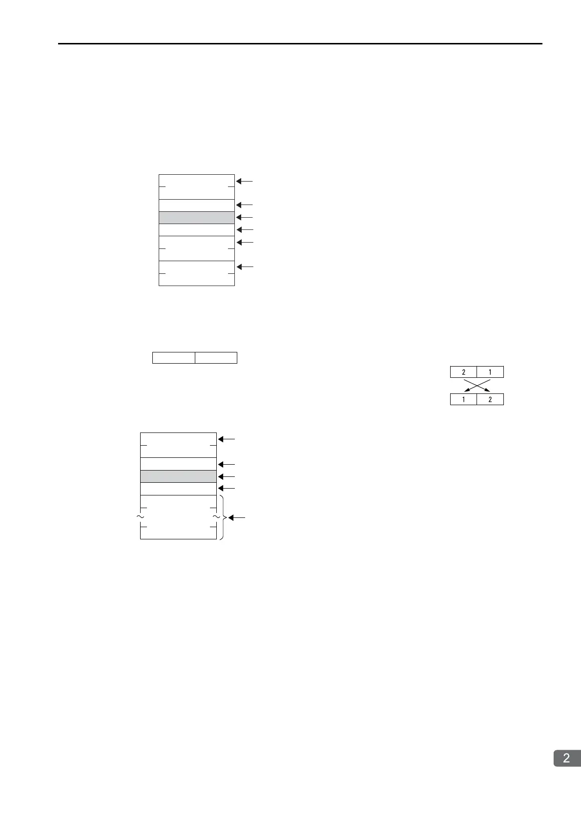
Reading the States of Coils
*1. MFC: Major function code
*2. SFC: Sub function code
*3. The CPU number is arranged as follows:
7 ••••••••• 0
(L)
(H)
(L)
(H)
(L)
(H)
Command
MFC*
1
: 20 hex
SFC*
2
: 01 hex
CPU number*
3
Length: 07 hex
Reference address
Number of coils (n)
Set the length of the command.
Always 20 hex.
The sub function code to read the states of coils is 01 hex.
Specify 4 bits each for the destination CPU number and the source CPU number.
Set the first address of the coils to read.
Set the number of coils to read.
Example
In this example, CPU 1 is the source and it will
send a message to CPU 2, the destination.
Command side: CPU number setting
Response side: CPU number setting
7430
Destination
Source
7•••••••••0
(L)
(H)
Response
Length: 03 hex +
((number of coils + 7)/8)
MFC: 20 hex
SFC: 01 hex
CPU number
(Coils 1 to 8)
Coils
(up to number of coils)
Set the length of the response.
Drop the portion after the decimal point.
Always 20 hex.
The response will contain the sub function code that was set in the command.
Specify 4 bits each for the destination CPU number and the source CPU number.
This contains the states of the coils that were read.

 Loading...


