2.16 Details on Protocols
Extended MEMOBUS Protocol
2-400
MEMOBUS ASCII Mode
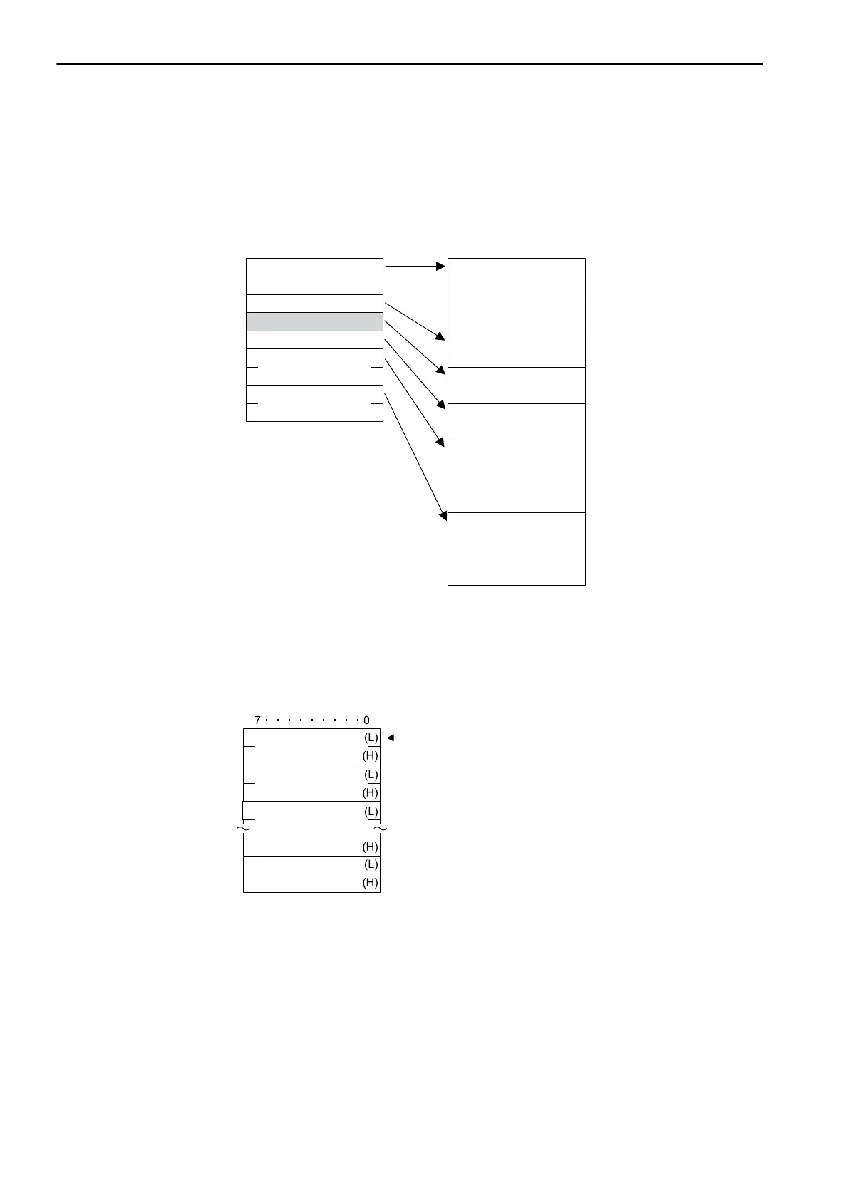
In ASCII Mode, binary data is converted to ASCII before being sent or received.
The following diagram illustrates the conversion from binary to ASCII. As shown in the example, 8-bit
data is converted into two 7-bit ASCII characters. The example shows the conversion of only the applica-
tion data field. In actual conversion, however, the EIF header is also converted to ASCII.
General-purpose Message Binary Mode
In the general-purpose message mode, the values of the MW hold registers in the Machine Controller are
sent and received in the application data field that follows the EIF header.
MFC
SFC
07 hex
00 hex
20 hex
03 hex
12 hex
00 hex
6B hex
03 hex
00 hex
7•••••••••0 7•••••••••0
30 hex
37 hex
30 hex
30 hex
MFC
32 hex
30 hex
SFC
30 hex
33 hex
31 hex
32 hex
30 hex
30 hex
36 hex
42 hex
30 hex
30 hex
30 hex
33 hex
Length
CPU number
Reference
address
Number of
registers
Length
CPU number
Reference
address
Number of
registers
Command
Contents of
MW
Contents of
MW + 1
Contents of
MW + n - 1
The contents of the MW
to MW + n -1 hold
registers in the Machine Controller are
set in these fields.
No response is returned when a
message is sent.

 Loading...


