2.16 Details on Protocols
MEMOBUS Protocol
2-409
MEMOBUS ASCII Mode
In ASCII Mode, RTU data is converted to ASCII before being sent or received.
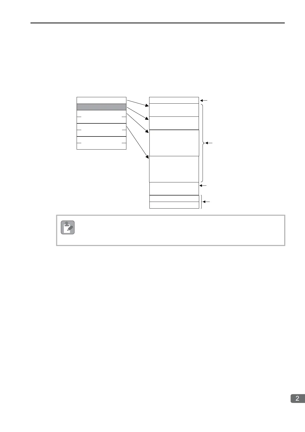
The following diagram illustrates the conversion from RTU to ASCII. As shown in the example, 8-bit data
in the application data field is converted into two 7-bit ASCII characters. In the MEMOBUS format, the
code for a “:” is added to the beginning of the data to indicate where the data starts, and the codes CR and
LF are added to the end of the data to indicate where it ends. Error checking is done with the LRC.
When a message is received on a 218IFD Module using the MEMOBUS protocol, the LRC is not
checked.
3A hex
:
30 hex
32 hex
30 hex
33 hex
7•••••••••0 7•••••••••0
02 hex
03 hex
00 hex
6B hex
24 hex
74 hex
CRC-16
00 hex
03 hex
30 hex
30 hex
30 hex
33 hex
30 hex
30 hex
36 hex
42 hex
LRC
38 hex
44 hex
0A hex
0D hex
CR
LF
Slave address
Function code
First address
Number of
data items
Slave address
Function code
First address
Number of
data items
Marks the beginning
of the message.
The 8-bit RTU data
is converted to
ASCII characters.
Error checking
in ASCII Mode
Marks the end of
the message.

 Loading...


