3.2 Function Modules
3.2.5 Data Logging
3-76
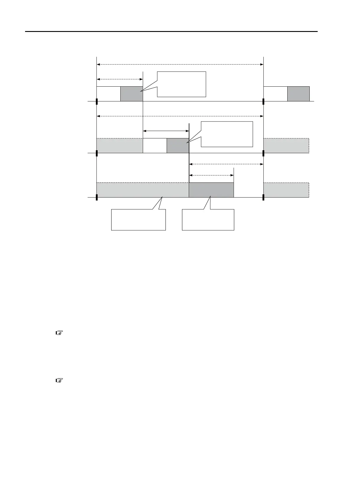
This timing chart illustrates the logging process when performed asynchronously with the scan.
The logging process for sampling the data is performed within the scan, while the process of
writing the data to a file is performed in background processing.
The background process is performed during the idle processing time of the scan. Therefore,
the idle processing time (time period A in the above figure) must be longer than the logging
overhead (time period B in the above figure).
If the logging overhead time is longer than the idle processing time of the scan, the file writing
process can run into the next scan and cause an over limit error. The number of over limit errors
can be checked in the over limit counter (SW24008).
Monitoring the Logging Execution Status
You can monitor the execution status of data logging by checking the system registers. Refer
to the following section for details.
Data Logging Execution Status on page 4-57
Viewing the Log Data
To view the log data in a PC, the data that is stored in the RAM in the CPU Module or USB
memory device must be transferred to the PC. Refer to the following section for details on data
transfers.
3.2.7 File Transfer on page 3-84
DWG.H
DWG.L
DWG.H
High-speed scan
Current high-speed
scan time
This process samples
target data and loads it
into a logging buffer.
This process samples
target data and loads it
into a logging buffer.
Low-speed scan cycle
Current low-speed
scan time
A: Idle processing time
B: Logging overhead
Logging
(le writing)
The shaded portion shows
that the higher priority
processing is interrupting
lower priority processing.
This process writes data
that was sampled during
the scan to the log le.
Low-speed scan
Background
processing
High-speed scan cycle
Logging
(data
sampling)
Logging
(data
sampling)
Logging
(data
sampling)

 Loading...


