7.3 External Dimensions
7.3.1 Small-Capacity, Coreless Servomotors
7-18
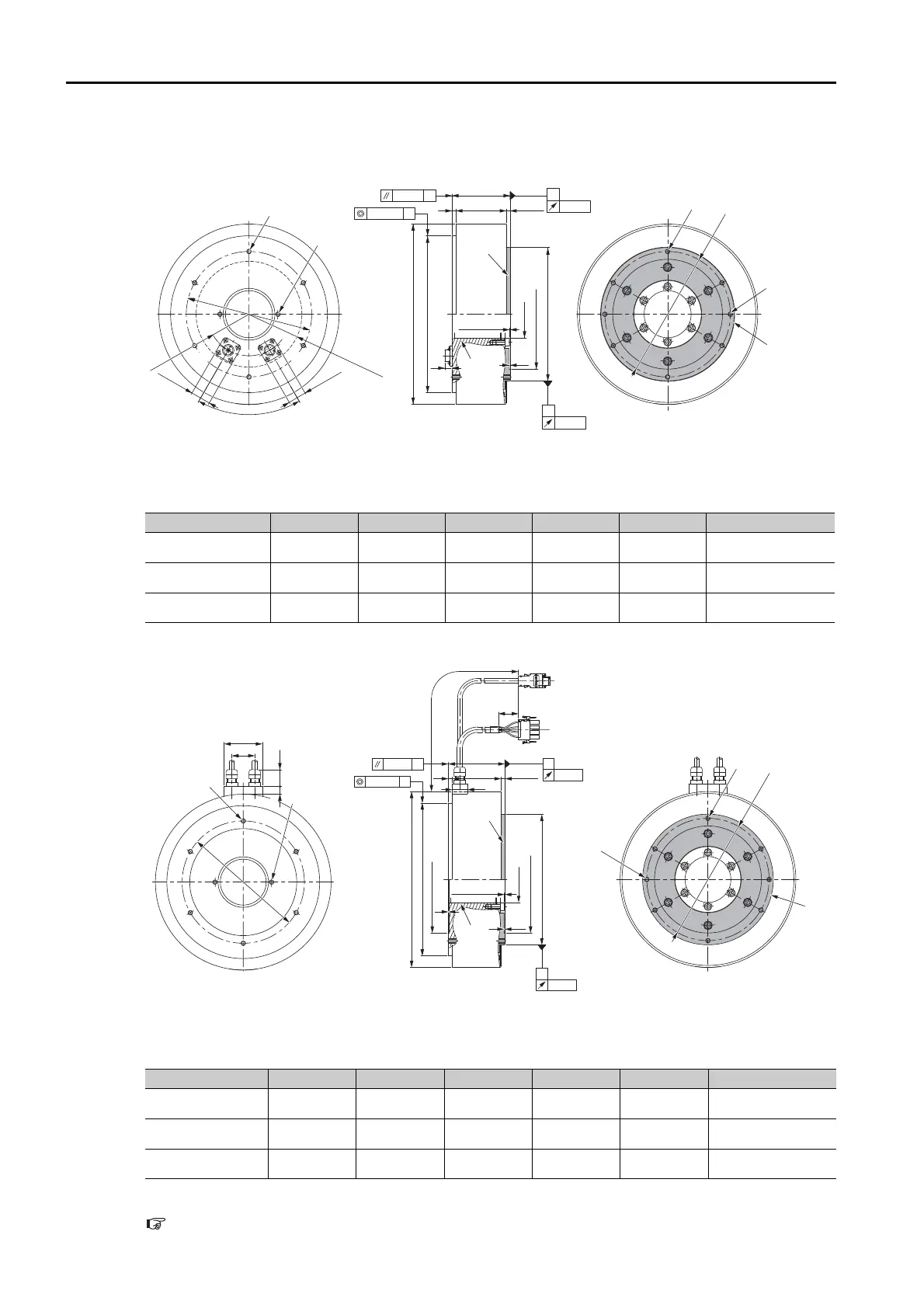
SGMCS-
D
• Flange Specification 1
*1. The shaded section indicates the rotating parts.
*2. The hatched section indicates the non-rotating parts.
Note: Values in parentheses are reference dimensions.
• Flange Specification 4
*1. The shaded section indicates the rotating parts.
*2. The hatched section indicates the non-rotating parts.
Note: Values in parentheses are reference dimensions.
Refer to the following section for information on connectors.
7.3.3 Connector Specifications on page 7-22
Model SGMCS- L (LL) LB LH LA Approx. Mass [kg]
08D
C11 74 64
20060170
14.0
17D
C11 110 100
20060170
22.0
25D
C11 160 150
20060170
29.7
Model SGMCS- L (LL) LB LH LA Approx. Mass [kg]
08D
C41 74 64
20060170
14.0
17D
C41 110 100
20060170
22.0
25D
C41 160 150
20060170
29.7
(2
×
M6
×
10)
(For use by Yaskawa)
6
×
M6
×
10
(Divided into equal
sections at 60°.)
R67.5 max.
connector area
(2
×
M6
×
10)
(For use by Yaskawa)
6
×
M6
×
10
(Divided into equal
sections at 60°.)
*2
23.4
0.08 dia.
230 dia.
LB dia.
LH
dia.
LA dia.
160 dia.
(0.5: bolt section)
(140 dia.)
*1
Unit: mm
(LL)
L
5
5
±
0.9
60
°
R53
*1
(9)
(1)
25.4
A
0.08 B
B
0.02
0.04
A
160 dia.160 dia.
160 dia.
5
20
(LL)
L
(0.5: bolt section)
0.1
(1)
5
±
0.9
300
±
50
(35)
*1
*1
*2
6
×
M6
×
10
(Divided into equal
sections at 60°.)
B
0.02
0.08 B
A
0.08 dia.
230 dia.
LB dia.
LA dia.
LH
dia.
A
0.04
160 dia.
(140 dia.)
(140 dia.)
(2
×
M6
×
10)
(For use by Yaskawa)
Unit: mm
6
×
M6
×
10
(Divided into equal
sections at 60°.)
(2
×
M6
×
10)
(For use by Yaskawa)
30
50
(22)
10
160160 dia. dia.
160 dia.