A1-1
The Drive control circuits use various parameters to select functions and characteristics of the
Drive. Changing of parameter settings must be done in the Program mode, or by use of the
Function LEDs, if available (see Section 4).
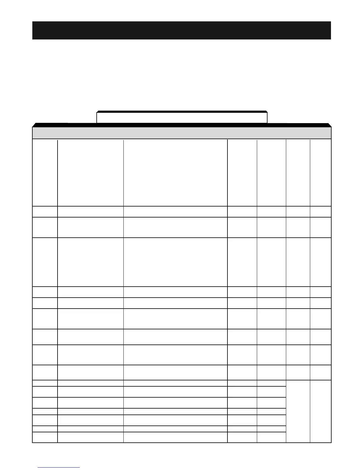
The following table lists all parameters in numerical order. For each parameter, reference
paragraph(s) in Section 5 are listed (if applicable) where the features of the Drive affected by that
parameter are described.
Appendix 1. PARAMETER LISTING
PARA- SETTING RANGE SETTING FACTORY USER PARA.
METER NAME (AND UNITS) INCREMENT SETTING SETTING REF.
0: n001 can be read and set;
n002 - n179 read only
1: n001 - n039 can be read and set
2: n001 - n079 can be read and set
3: n001 - n119 can be read and set
n001 Parameter Selection / 4: n001 - n179 can be read and set
Initialization 5: n001 - n179 can be read and set 1 1 5.21
Run command accepted during Program mode
6: Clear Fault History Only
7: Not Used
8: 2-wire Initialization (Japan Spec.)
9: 3-wire Initialization (Japan Spec.)
10: 2 wire initialization (USA Spec)
11: 3 wire initialization (USA Spec.)
n002 Control Method Selection
0: V/f Control
10 2.2
1: Open Loop Vector
0: Digital Operator
n003 Operation Method Selection 1: Terminal 1 1 5.13
2: Serial Communication (Modbus)
3: Option Card
0: Digital Operator Pot
1: Digital Operator
2: Voltage Reference (0 to 10V)
3: Current Reference (4 to 20 mA)
n004 Reference Selection
4: Current Reference (0 to 20 mA) 5.11,
5: Pulse Train Reference 1 2 5.13
6: Serial Communications (Modbus)
7: Multi-Function Analog Input (0 to 10V)
8: Multi-Function Analog Input (4 to 20 mA)
9: Option Card
n005 Stop Method
0: Ramp to stop
10 5.24
1: Coast to stop
n006 Reverse Prohibit
0: Reverse Run enabled
10
1: Reverse Run disabled
0: STOP key is effective regardless of
programming of n003
n007 STOP Key Function
1: STOP key is effective only when sequence
10 5.13
command (per n003) is from Digital Operator
0: Frequency Reference from digital
n008
Reference Selection -
operator pot 1 0 5.13
Digital Operator
1: Frequency Reference from n024
0: ENTER key must be pressed to write-in
n009
Frequency Reference Setting new value
10 5.13
Method From Digital Operator 1: ENTER key does not have to be pressed
to write-in new value
Operation Selection 0: Disabled (operation continues)
n010 When Digital Operator is 1: Enabled (motor coasts to a stop and fault 1 0 5.15
Disconnected is displayed)
n011 Frequency - Max. 50.0 to 400.0 0.1 (Hz) 60.0
n012
Voltage - Max.
0.1 to 255.0 (230V drive)
0.1 (V)
230.0
0.2 to 510.0 (460V drive) 460.0
n013
Frequency - Max.
0.2 to 400.0 0.1 (Hz) 60.0
Voltage Point
n014 Frequency - Midpoint 0.1 to 399.9 0.1 (Hz) (Note 2) 5.27
n015
Voltage - Midpoint
0.1 to 255.0 (230V drive)
0.1 (V) (Note 2)
0.2 to 510.0 (460V drive)
n016 Frequency - Min. 0.1 to 10.0 0.1 (Hz) (Note 2)
n017
Voltage - Min.
0.1 to 50.0 (230V drive)
0.1 (V) (Note 2)
0.2 to 100.0 (460V drive)
Table A1-1. V7 Parameters