5-22
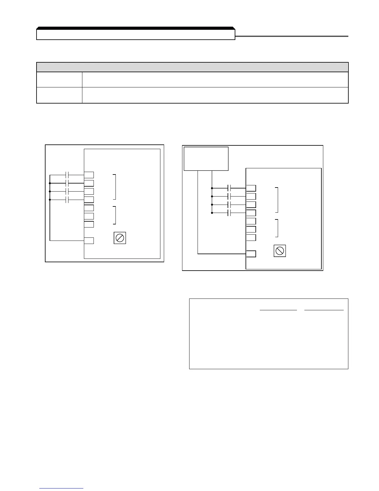
The multi-function input terminals can be activated in one of two ways:
The multi-function inputs are configured using rotary switch SW1, which is located above the upper
row of control circuit terminals and can be set with a small screwdriver.
NOTE: All power must be removed from the Drive before SW1 can be set.
(1)
Customer supplied component
n050 : Te rminal S1 Function Factory settings:
2-Wire control 3-Wire control
n051 : Te rminal S2 Function n050 11
n052 : Te rminal S3 Function n051 22
n053 : Te rminal S4 Function n052 30
n054 : Te rminal S5 Function n053 55
n055 : Te rminal S6 Function n054 66
n056 : Te rminal S7 Function n055 77
n056 : Te rminal S7 Function n056 10 10
These seven parameters select the input signal function for terminals S1 thru S7, and can be inde-
pendently set.
Parameter settings are checked whenever the enter key is pressed. A parameter set failure (Err) will
occur if any of the following conditions are detected:
•Two parameters contain the same value (n050 thru n056).
• Both the Accel/Decel Hold (data 16) and the Up/Down (data 34) functions have been selected.
Table 5-2 lists the possible data setting values and their descriptions for these parameters.
5.18 MULTI-FUNCTION INPUT TERMINALS (Term. S1-S7)
Type of input Description
NPN A contact closure must be made between a multi-function terminal (S1 to S7) and SC in order
(Factory Setting) to activate that input.
PNP
A DC voltage (+24v, 8mA max. current) must be present on a multi-function input terminal (S1 to S7)
in order to activate that input. NOTE: The minus (-) side of the 24 VDC supply must be connected to SC.