1-6
The Drive leaves the factory with all parameters set for 2-Wire external reference control. Figure 1-5
must be used for all external connections.
To use the Drive in a 3-Wire application, drive parameters n001, n003, and n004 must be
reprogrammed, using the Digital Operator. Figure 1-6 must then be used for all external connections.
IMPORTANT
When a cable gland is used for water and dust tight type (NEMA type 4X/12) models, observe the
following:
• Use multi-core cable for cable gland. (If more than one cable is inserted into one cable gland,
a gap is created and may cause leakage.)
• Seal the cable gland with a gasket without fail. (A gasket is attached to the recommended
cable gland.)
A. Main Circuit Input /Output Wiring
Complete wire interconnections according to Table 1-2, Figure 1-5 thru Figure 1-7. Be sure to
observe the following:
• Use 600V vinyl-sheathed wire or equivalent. Wire size and type should be determined by local
electrical codes.
•Avoid routing power wiring near equipment sensitive to electrical noise.
•Avoid running input and output wiring in the same conduit.
• NEVER connect AC main power to output terminals T1(U), T2(V), and T3(W).
• NEVER allow wire leads to contact metal surfaces. Short-circuit may result.
• NEVER connect power factor correction capacitors to the drive output. Consult Yaskawa when
connecting noise filters to the drive output.
• WIRE SIZING MUST BE SUITABLE FOR CLASS I CIRCUITS.
•When connecting motor to drive’s output terminals, include a separate ground wire. Attach
ground wire solidly to motor frame and to drive’s ground terminal .
•When using armored or shielded cable for connection between drive and motor, solidly connect
armor or shield to motor frame, and to drive’s ground terminal .
• Motor lead length should NOT EXCEED 164 feet (50 meters), and motor wiring should be run in
a separate conduit from the power wiring. If lead length must exceed this distance, reduce carrier
frequency (see paragraph 5.8) and consult factory for proper installation procedures.
• Use UL listed closed loop connectors or CSA certified ring connectors sized for the selected wire
gauge. Install connectors using the correct crimp tool recommended by the connector manufacturer.
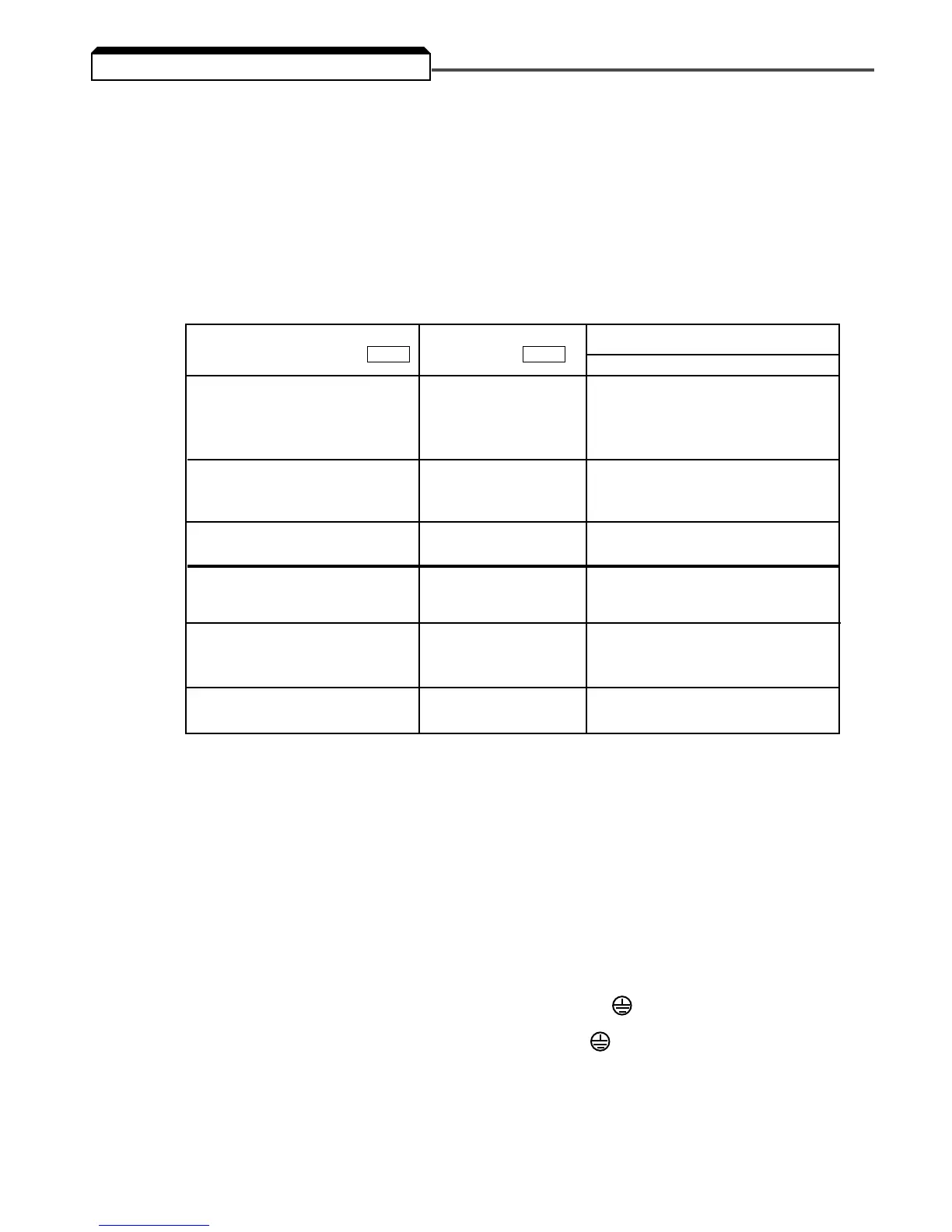
1.4 ELECTRICAL INSTALLATION
Model CIMR-V7* MV
Dimensions in inches (mm)
Qty-Dia
20P1 A001
20P2 A002 3-0.89 DIA
20P4 A003 (3-Ø 22.6)
20P7 A005
21P5 A008
22P2 A011
23P7 A017
25P5 A025 3-1.38 DIA
27P5 A033 (3-Ø 35)
40P2 B001
40P4 B002
40P7 B003
41P5 B005
42P2 –
43P7 B009
45P5 B015 3-1.38 DIA
47P5
–
(3-Ø 35)
Cable Gland Mounting Hole
3-1.06 DIA
(3-Ø 26.8)
3-0.89 DIA
(3-Ø 22.6)
3-1.06 DIA
(3-Ø 26.8)