- vi -
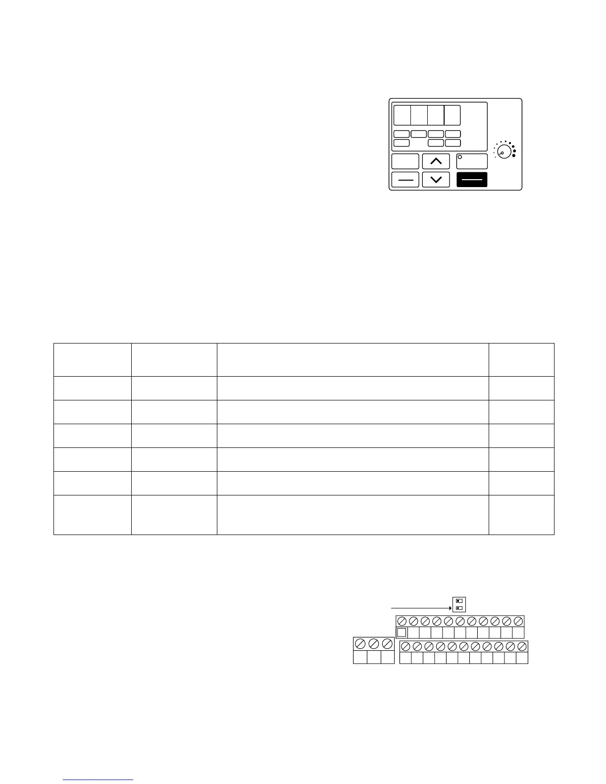
❏ Digital Operator
The DSPL button cycles through all of the quick start LEDs.
To access a parameter, press the DSPL button until the
PRGM LED is on. Use the UP and DOWN keys until the
desired parameter number is displayed, then press
ENTER. Use the UP and DOWN keys to adjust the value
then press ENTER then DSPL.
Before the drive will accept a RUN command, one of the
following LEDs must be on: FREF, FOUT, IOUT, MNTR, or F/R. For more specific
information on the digital operator, see Section 4.
❏ Choose a configuration from Table 1 below. Each example listed below contains a
control wiring diagram, operation explanation, and all necessary programming. The
Drive can be controlled in many more ways than is described in these examples, see
Paragraph 5.11, Frequency Reference Selection, and Paragraph 5.13, Local/Remote
Reference and Sequence Selection.
Table 1: Drive Configuration Examples
* For a more detailed explanation of sequence and reference, consult the Definitions Section.
❏ Control Terminal Wiring – Remove power and
wait for all LEDs to go out before making control
terminal connections. Control wiring should be
sized 16 to 20 AWG. Control wiring should be
shielded, with the shield wire connected to the
ground terminal, which is located towards the
left side of the aluminum heat sink.
❏ Control Method – This document assumes that the drive will be left in the volts per
hertz (V/f) control method. For a further explanation of control method or to change the
control method, consult Section 2.1.
0. 0 0
Sequence* Reference*
Source Source Description
Example
(Run / Stop) (Motor Speed)
Digital Operator Digital Operator Example 1
2-wire Digital Operator Example 2
3-wire Digital Operator Example 3
2-wire 4-20 mA Example 4
3-wire Example 5
2-wire Example 6
This method requires no control wiring connections to the
drive. It is most often used during startup of the drive.
Remote Speed
Potentiometer
0 – 10V DC
with several
digital presets
With this method, the drive can be started and stopped
using an external (remote) signal.
This method is the same as Example 2 above, but uses
pushbuttons instead.
This method is the same as Example 2, but the reference
comes from a remote 4 – 20 mA source such as a PLC.
This method is similar to Example 3, but utilizes a remote
mounted speed control (potentiometer).
This method is similar to 2, but allows switching between
an analog reference and three digital preset references.