5-41
Continued
n011 : Frequency – Max. (Fmax)
n012 : Voltage – Max. (Vmax)
n013 : Frequency – Max. Voltage point (F
A)
n014 : Frequency – Midpoint (F
B
)
n015 : Voltage – Midpoint (V
C)
n016 : Frequency – Min. (Fmin)
n017 : Voltage – Min. (Vmin)
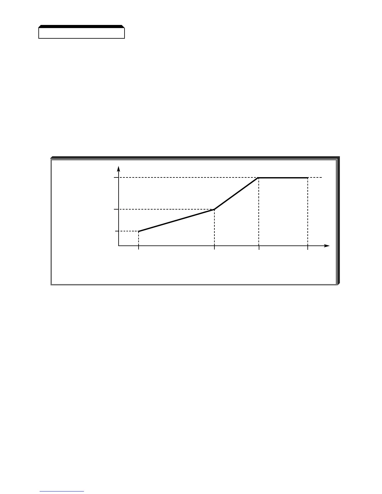
These seven parameters define the V/f pattern. The illustration below shows how these constants
relate to each other in establishing the custom V/f pattern.
NOTE: To establish a V/f pattern with a straight line from Fmin to F
A, set
F
B = Fmin. The setting of VC is then disregarded and does not affect the
V/f pattern.
IMPORTANT
The V/f parameter settings are checked each time the ENTER key is
pressed while programming the V/f parameters. A parameter set value
failure (Err ) will occur if any part of the following relationships among
n011 thru n017 is not TRUE:
(a) Fmax ≥ F
A ≥ FB ≥ Fmin
(b) Vmax ≥ V
C ≥ Vmin
5.27 V/f PATTERN
V/f Characteristics Set by n011 thru n017
Vmax
(n012 )
OUTPUT
VOLTAGE V
C
(n015 )
Vmin
(n017 )
Fmin F
B FA Fmax
(n016 )(n014 )(n013 )(n011 )
OUTPUT FREQUENCY