188
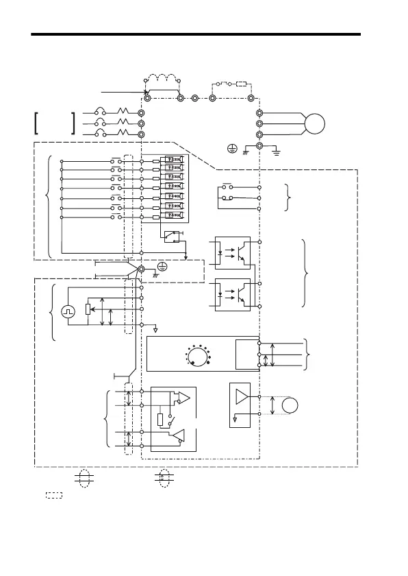
Standard Wiring
R
S
T
S1
+2 +1 B1 B2−
S2
S3
S4
S5
S6
S7
SC
SW1
NPN
+24V
PNP
RP
FS
FR
PP
2kΩ
FC
R+
R-
S+
S-
MIN MAX
FM
P
P
0 V
4 to 20 mA
0 to 10 V
P
GND
IIN
VIN
AM
PC
MC
MB
MA
W/T3
V/T2
U/T1
T/L3
S/L2
R/L1
UX
P1
P2
1
2
3
AC
CN2
0V
Frequency Setting
Potentiometer
Reference Pulse Train
(Max. 33 kHz)
Frequency Reference
0 to +10 V (20 kΩ)
4 to 20 mA (250 Ω)/0 to 20 mA (250 Ω)
Frequency Setting Power
Supply (+12 V 20 mA)
Digital Operator
Frequency
Setting
Potentiometer
IM
P
P
FORWARD RUN/STOP
REVERSE RUN/STOP
FAULT RESET
MULTI-STEP
SPEED REF. 1
MULTI-STEP
SPEED REF. 2
JOG
COMMAND
For Single-
phase.
Use R/L1
and S/L2.
Multi-function input
EXTERNAL FAULT
(NO CONTACT)
Power Supply
DC Reactor
(Optional)
Thermal
Overload
Relay
Braking Resistor
(Optional)
Short-circuit bar
*1
MCCB
Frequency Ref.
Pulse Train Input
MEMOBUS
Communications
RS-485/422
Max. 19.2 kbps
Grounding
Multi-function
Contact Output
*2
250 VAC 1 A or less
30 VDC 1 A or less
FAULT
RUNNING
FREQUENCY
AGREED
Multi-function
Photocoupler
Output
+48 VDC 50 mA
or less
Analog Monitor
Output
0 to +10 VDC (2 mA)
Multi-function
analog input
Output
Frequency
Analog Monitor/Pulse
Monitor Selectable
Shield connection
terminal
Terminal Resistance
(1/2 W, 120 Ω)
Shielded twisted-pair cable
Shielded
: Only basic insulation (protective class 1, overvoltage category II) is provided for the
control circuit terminals. Additional insulation may be necessary in the end product to
conform to CE requirements.
*1. Short-circuit bar should be removed when connecting a DC reactor.
*2. Minimum permissible load: 5 VDC, 10 mA (as reference value)
P

 Loading...


