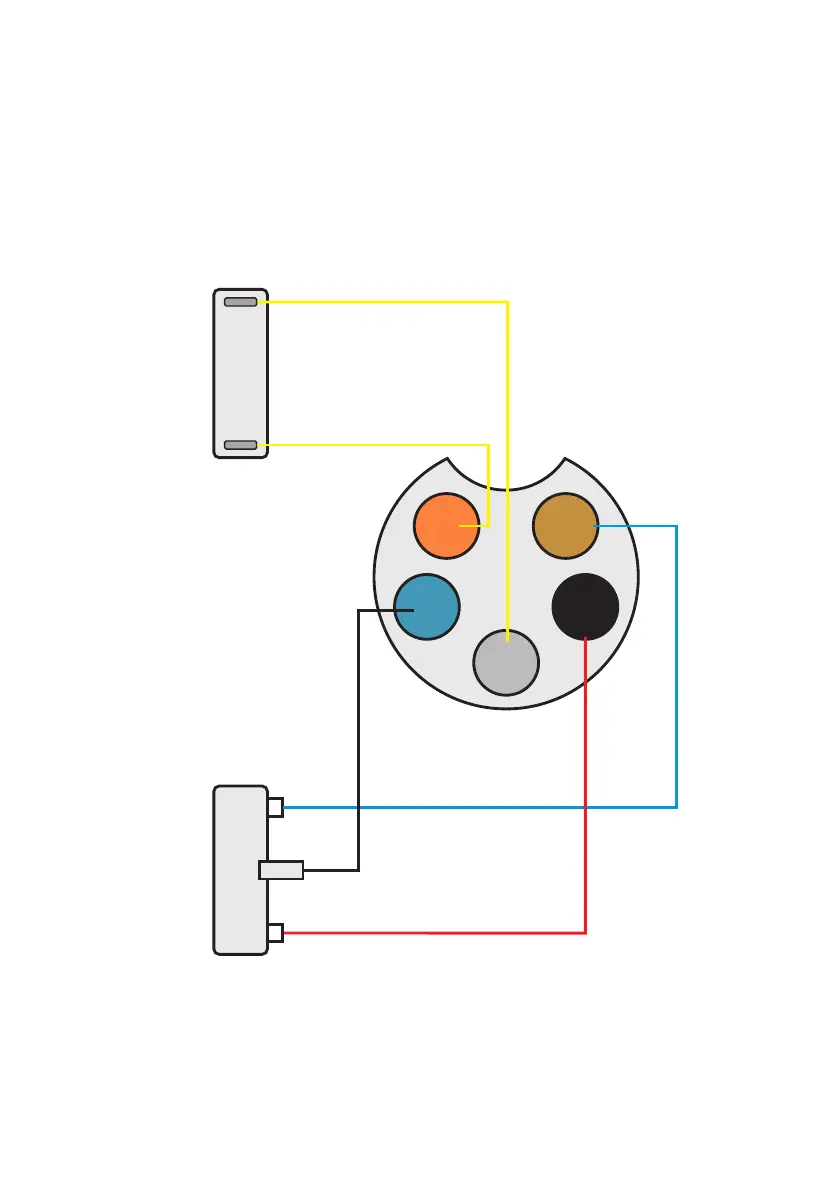
Foot Pedal Wiring Requirements
To ensure proper functionality and connection with the machine, the foot pedal must meet specific conditions:
Ÿ Internal Structure: The foot pedal must contain an inching switch and a 10K sliding potentiometer, designed for precise control of
welding current and switching in TIG mode.
Ÿ Connector Specification: The pedal requires a 5-pin connector for wiring.
Ensure the pedal meets these specifications to achieve reliable operation and compatibility with the machine. Refer to the diagram
below for the correct pin configuration.
3
1
R: 2W 10K
2
SWITCH
BLACK
RED
BLUE
YELLOW
5
4
YELLOW
ELECTRICAL DIAGRAMS
- 43 -
 Loading...