7-1
IM 2558A-01EN
Synchronous Operation
7
8
9
10
11
12
13
14
15
16
App
Index
7.1 External Signal Input and Internal Signal
Output
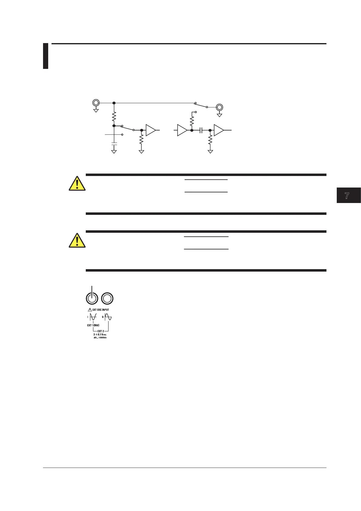
I/O Circuit Diagram
10 kΩ
50 Ω
10 μF
220 pF
1 MΩ
100 kΩ
ext
ext
int
int
External Signal Input
CAUTION
The input voltage is 3 Vrms, and the input resistance is approximately 1 MΩ. Do not apply
excessive voltage.
French
ATTENTION
La tension d’entrée est de 3 Vrms et la résistance d’entrée est de 1 MΩ environ. Ne pas
appliquer de tension excessive.
Connect the external oscillator to this terminal.
Input Section (EXT OSC INPUT)
Input voltage: 3 ± 0.1 Vrms, sine wave
Frequency range: 40 Hz to 1000 Hz
Input resistance: Approx. 1MΩ
There are two ways to apply external signals.
• Connecting an external oscillator
Set the frequency to EXT1. For details, see section 2.2 and “Selecting External Oscillator EXT1” in
section 5.2.
• Connecting another 2558A as the master oscillator (synchronous operation)
Set the frequency to EXT2 (PHASE). For details, see section 2.2 and “Selecting External Oscillator
EXT2” in section 5.2. For details on the connection for synchronous operation, see section 7.2.
Chapter 7 Synchronous Operation
 Loading...