7-11
IM CW240E
Measurements
7
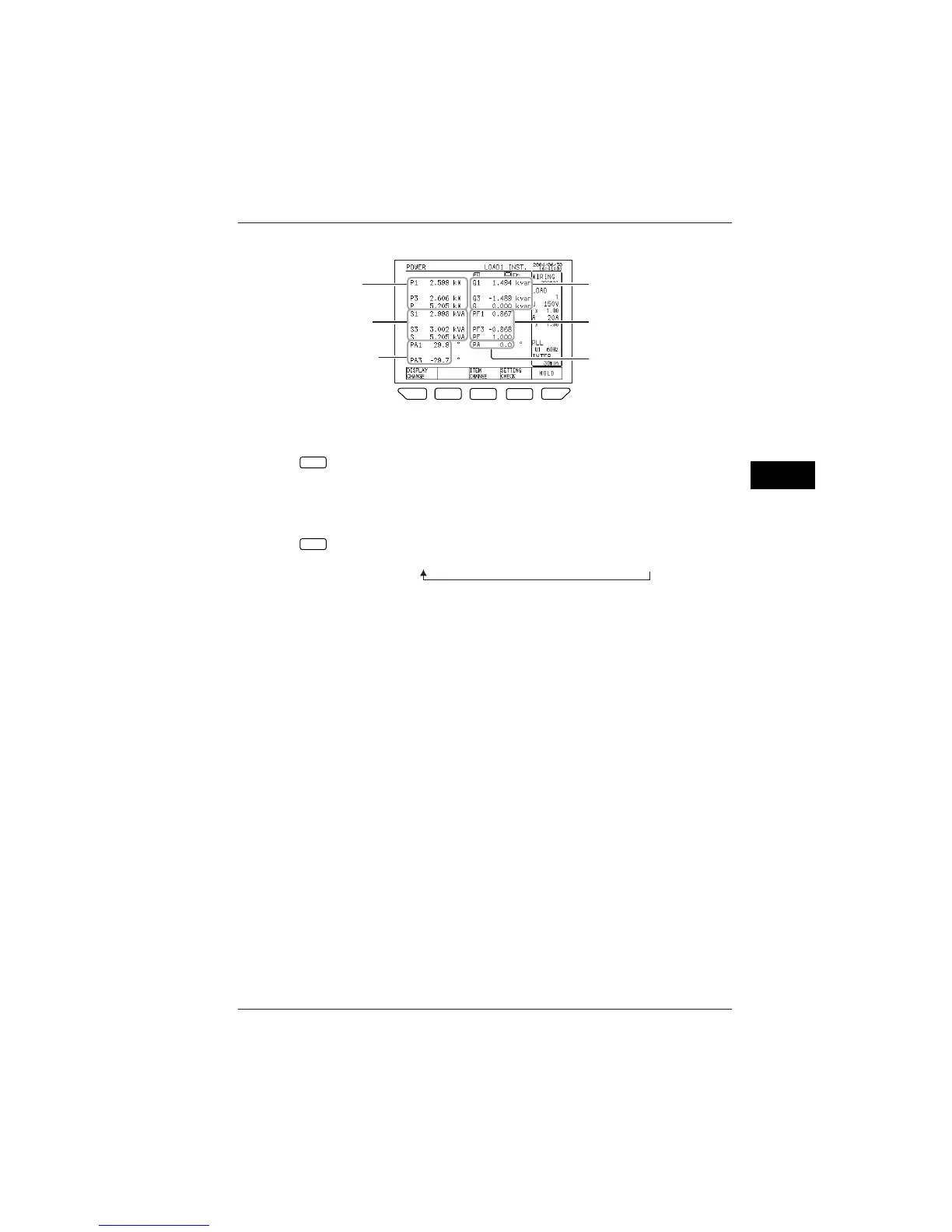
● Description of the Power Screen
F
1
F
1
F
2
F
3
F
4
F
5
Q1 to Q3: reactive power
Q: total reactive power
PF1 to PF3: power factors
PF: total (power factor)
PA: total (phase angle)
S1 to S3: apparent power
S: total apparent power
PA1 to PA3: phase angles
P1 to P3: active power
P: total active power
To switch the load to be displayed:
F
2
The load (measured value) changes each time the F2 key is pressed.
(The display varies depending on the wiring setting or the number of
loads.)
To switch the item to be displayed:
F
2
The item changes each time the F3 key is pressed:
Instantaneous value → Average → Maximum value → Minimum value
For instantaneous value measurements, the AVE, MAX., and MIN. values
indicate the measured values of integration measurement conducted
immediately before that. (If no integration measurement is made
immediately before that, symbol ----- appears.)
7.2 Measure Screens

 Loading...