<5. Parameter Summary>
5-2
IM 01C25T01-06EN
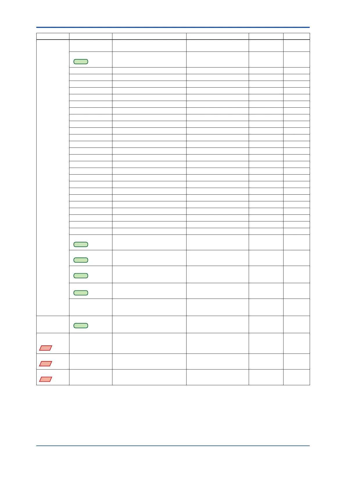
Function Label Item Contents Default value Handling *
1
Device
information
Chg universal rev *
4
Change the HART universal
revision
HART 5 or HART 7 M
Country
HART 7
Country code US, JP, DE, FR, ES, RU, CN JP W
Dev id Device ID R
Distributor Yokogawa R
Drain vent matl Drain and vent plug material W
Extra No. Customizaion number R
Ext SW External zeroing permission Disabled or Enabled Enabled W
Fill uid Fill uid W
Final asmbly num Final assembly number W
Fld dev rev Field device revision R
Gasket matl Gasket material W
Isoltr matl Capsule material W
Mftr Date Manufactured date R
Model 1 Memo eld for MS code 1 32 alphanumerics W
Model 2 Memo eld for MS code 2 32 alphanumerics W
Model 3 Memo eld for MS code 3 32 alphanumerics W
Num of RS Number of remote seal W
Process Conn matl Process connection material W
Process Conn size Process connection size W
Process Conn type Process connection type W
RS ll uid Fill uid of remote seal W
RS Isoltr matl Remote seal material W
RS type Remote seal type W
Serial No. Serial number R
Sotware rev Software revision R
Style No. Style number Style number of product R
Universal rev Universal revision 16 alphanumerics R
Cfg chng count
HART 7
Conguration change counter 0 R
Reset Cfg chng ag
HART 7
Reset Conguration change ag M
Device Prole
HART 7
Device Prole Process
automation
device
R
Max dev vars
HART 7
Max device variables 3 R
Model Model Model name + Measurement
span in the Sux Codes
Ex) “EJX110 M”
R
Device
Variable
Simulation
Simulate
HART 7
Execution of device variable
simulation
Execute the simulation M
Diag
Applicable
EJX
Diag Applicable Appicable blockage detection Disabled or Enabled RG
Diag DPComp
EJX
Diag DPComp fDP compensation selection Compensation or
Non-compensation
Compensation WG
Diag Error
EJX
Diag Error Results detected by ILBD or Heat
trace monitoring
RG
*1: Handling:
R
=Read only,
W
=Read & Write,
M
=Method,
A
=Applicable for option code AL,
G
=Applicable for option code DG6,
D
=Applicable for dierential pressure transmitters. Do not change these parameters for pressure transmitters.
*2: Max three Burst Messages (Burst Message 1, Burst Message 2, Burst Message 3)
*3: The default value shows MWP (Maximum working pressure) of the capsule.
Since the working pressure limit varies according to the Model, refer to the General Specications section in each user’s manual.
*4: For output signal code J, refer to the section 3.3.18.
*5: These parameters may contain adjustment values based on the customer range calibration at the factory upon shipment.
When executing “Clear P sensor trim”, P LTD and P UTD will become “0”, and P LTP and P UTP will become the value of LRV and
URV respectively.

 Loading...


