C1-3
IM 34M06H62-02E 2nd Edition : June 2008-00
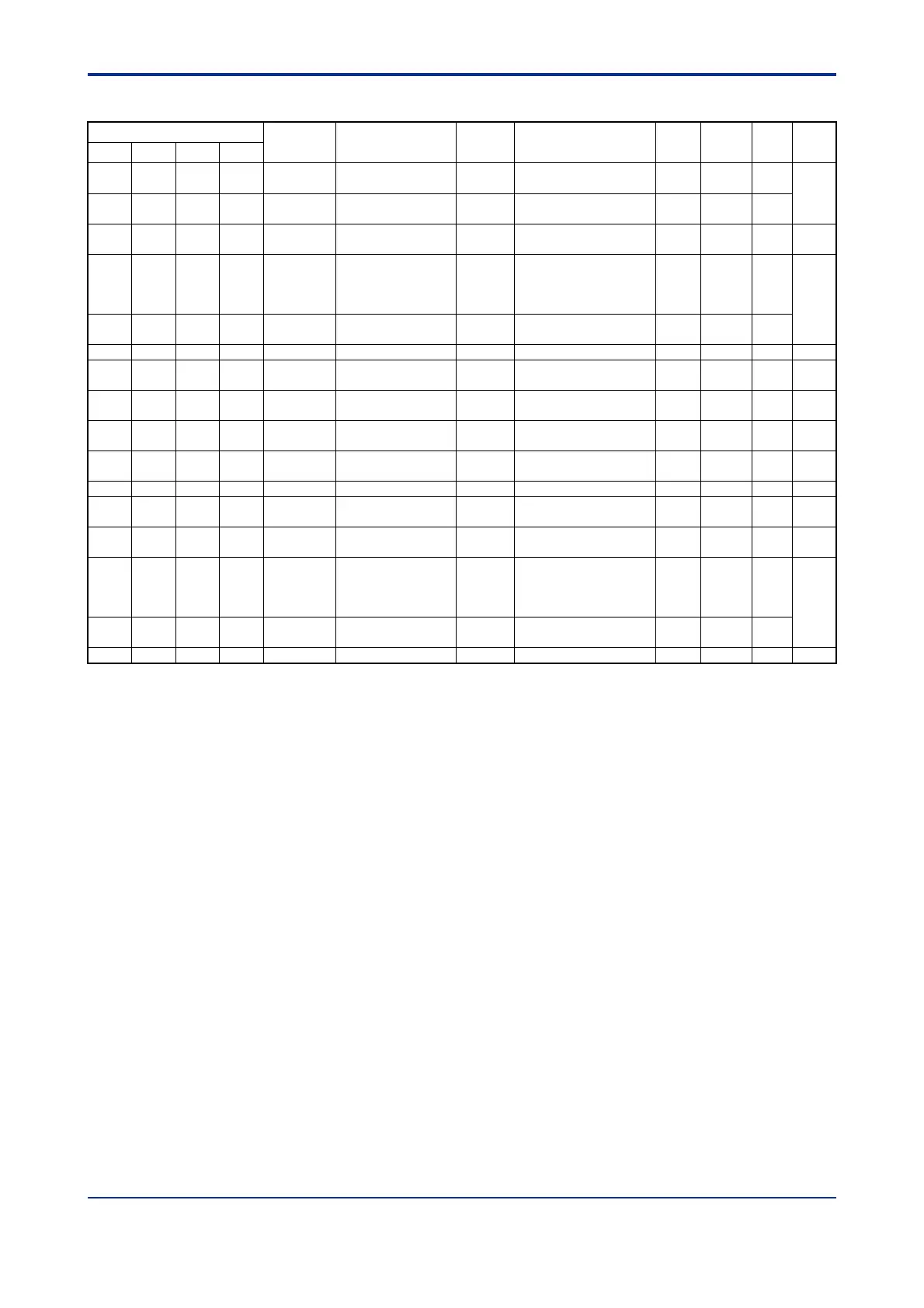
Table C1.3 Parameters Related to Single Loop
Data Position Number
Symbol Description Unit Data Range
Default
Value
Attribute Stored
See
Also
Loop1 Loop2 Loop3 Loop4
101 301 501 701 PVIN Input process value
Industrial
unit
-5 to 105% of (SL to SH) — RO —
C3
102 302 502 702 PV Process value
Industrial
unit
-5 to 105% of (PRL to
PRH)
— RO —
103 303 503 703 CSP Control set point
Industrial
unit
PRL to PRH — RO — C4
104 304 504 704 HOUT Control output %
OL to OH: for single
output
0 to OH: for
heating/cooling output
— RO —
C2
C7.1
105 305 505 705 COUT
Cooling control
output
%
0 to OL: For
heating/cooling output
— RO —
121 321 521 721 RUN/STP Run/stop selection None 0: Stop; 1: Run 0 RW — C7.1
122 322 522 722 A/M/C
Automatic/manual/
cascade selection
None
0: Automatic, 1: Manual
2: Cascade
*1
0 RW —
C7.2
C7.4
124 324 524 724 RMT/LOC
Remote/local
selection
None
0: Local
1: Remote
0 RW — C7.3
125 325 525 725 EXPV/PV
External/normal
input selection
None
0: Normal input
1: External input
0 RW — C3.12
126 326 526 726
EXOUT/
OUT
External/normal
output selection
None
0: Normal output
1: External output
0 RW — C2.6
128 328 528 728 SPNO SP number selection None 1 to 4 1 RW — C4.1
131 331 531 731 EXPV External input
Industrial
unit
-5 to 105% of (SL to SH) SL RW — C3.12
133 333 533 733 RSP Remote set point
Industrial
unit
PRL to PRH PRL RW — C4.2
134 334 534 734 MOUT Manual output %
OL to OH: for single
output
0 to OH: for
heating/cooling output
0 RW —
C7.2
C7.4
135 335 535 735 MOUTC
Manual cooling
output
% 0 to OL 0 RW —
136 336 536 736 EXOUT External output % -5.0 to 105.0% 0 RW — C2.6
*1 The controller mode must be set to Cascade Control before Automatic/Manual/Cascade Selection (A/M/C) can be
set to 2 (Cascade). In cascade control mode, operation proceeds according to the setup for the even-numbered
loop (2 or 4).
The single-loop mode is the most basic controller mode, where the module performs
computation using the control and computation function and outputs the control output
(HOUT and COUT) as defined by the output-control functions so that the process value
(PV) as processed by the Input PV-related functions approaches the control set point
(CSP) as defined by the SP-related functions.
The PV-related functions process the output from a thermocouple, RTD or other
temperature sensors according to the characteristics of individual sensors. In particular,
the filter function reduces noise and other disturbances, and the biasing functions correct
for deviations between devices. For details, see Section C3, "PV-related Functions."
The SP-related functions set up and select set points (SP), and perform processing to
prevent abrupt changes. In addition, the remote set point (RSP) can be used to receive
successive external set points. For details, see Section C4, "SP-related Functions."
The control and computation function computes control output values so that the PV
approaches the set point. The control method may be set to ON/OFF, PID, or
heating/cooling PID control to suit an application. For details, see Section C6, "Control
and Computation Function."
The output control functions process the output so that the upper limit, lower limit, or the
rate-of-change limit will not be exceeded. They also perform processing to prevent
sudden changes in the output level due to, say, switching between Automatic and Manual
mode. For details, see Section C2, "Output-related Functions."
 Loading...