C7-4
IM 34M06H62-02E 2nd Edition : June 2008-00
C7.2 Automatic/Manual Switch
Setting the Automatic/Manual/Cascade Selection (A/M/C) parameter to “1: Manual”
allows you to output any arbitrary value manually. Manual output operates only when the
Run/Stop Selection (RUN/STP) parameter is set to “Run”. If “Stop” is specified, the
preset output is output instead. (See Section C7.1, “Run/Stop Switch”)
When changing the Automatic/Manual/Cascade Selection (A/M/C) parameter from
“Automatic” to “Manual” in Run mode, the control output value remains the same before
and after the change. That is, the switch is “bump-less”.
In Manual mode, the PID computation function stops and the output value can be
changed manually using the Manual Output (MOUT) parameter and the Cooling Manual
Output (MOUTC) parameter. Specifying a manual output value beyond the range defined
by the Upper Output Limit (OH) and Lower Output Limit (OL) parameters will result in a
control output limited by OH and OL. The output rate-of-change limit is, however,
disabled in Manual mode.
In On/Off Control mode, only output values of 100% or 0% are allowed. (For details, see
paragraph “ Manual Operation” in Section C2.4.1, “On/Off Control Output”).
In Heating/Cooling PID Control mode, manual output is carried out on the heating output
or the cooling output. (For details, see “ Manual Operation” in Section C2.4.3,
“Heating/Cooling PID Control.”)
In Heating/Cooling On/Off Control mode, manual output can be carried out separately for
the heating output and the cooling output. Only output values of 100% or 0% are allowed.
(For details, see “ Manual Operation” in Section C2.4.4, “Heating/Cooling On/Off
Control.”)
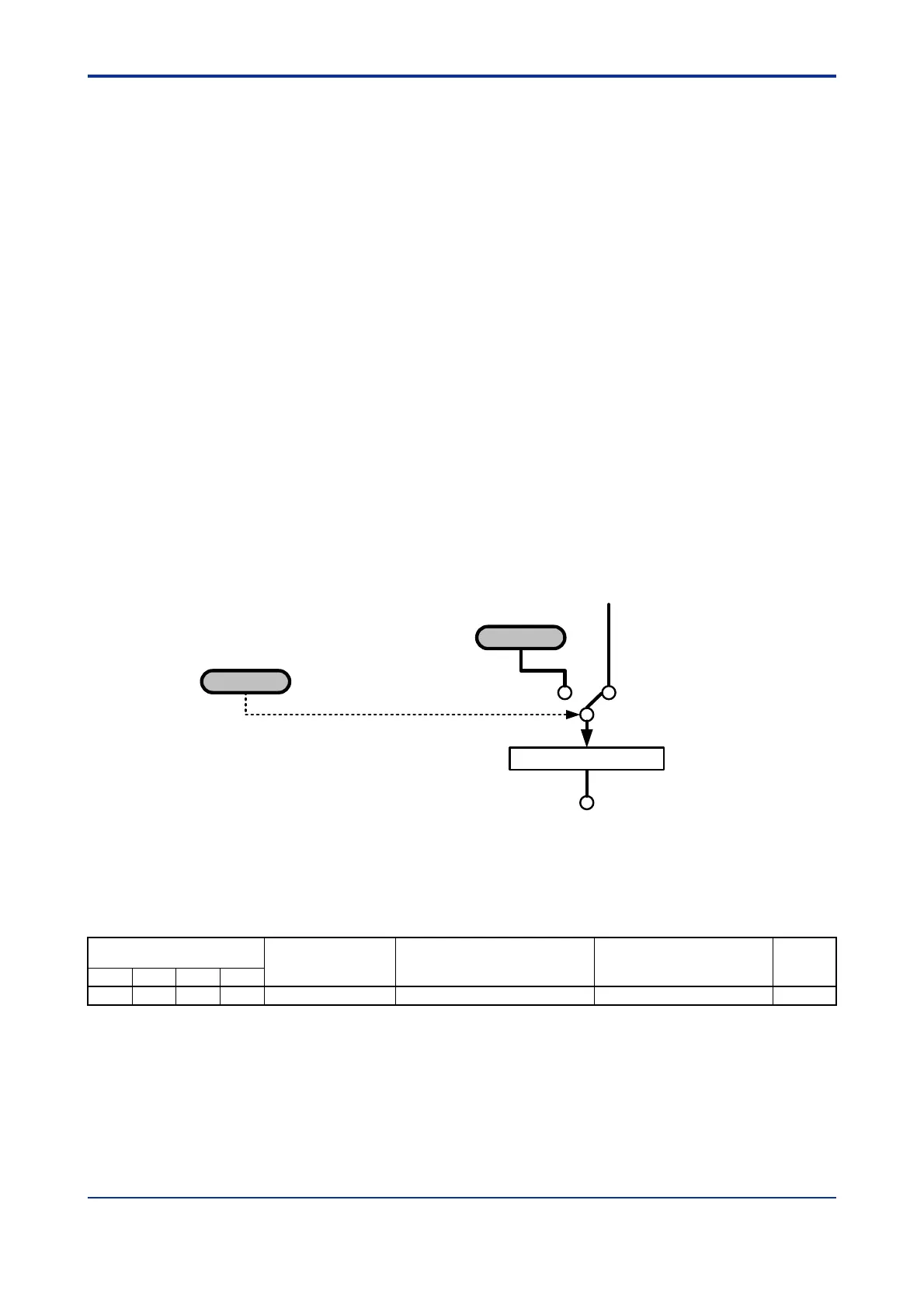
MOUT
AutomaticManual
Output Limiter
A/M/C
Switching between
Automatic and Manual
Result of PID
computation
Figure C7.6 Manual Operation Block Diagram
To check whether a loop is in Automatic or Manual mode, use the Auto/Manual (A/M)
input relay.
Table C7.3 Parameters Related to Automatic/Manual Switching
Input Relay Number
Xnn
*1
Symbol Description Data Range Interrupt
Loop1 Loop2 Loop3 Loop4
X03 X11 X19 X27 A/M Auto/Manual
*2
0: Automatic; 1: Manual —
*1 denotes the slot number where the module is installed.
*2 For details on how to check the operating status in Cascade Control mode, refer to descriptions on cascade control.
 Loading...