C7-5
IM 34M06H62-02E 2nd Edition : June 2008-00
C7.2.1 Operation after Switching from Manual Mode to
Automatic Mode
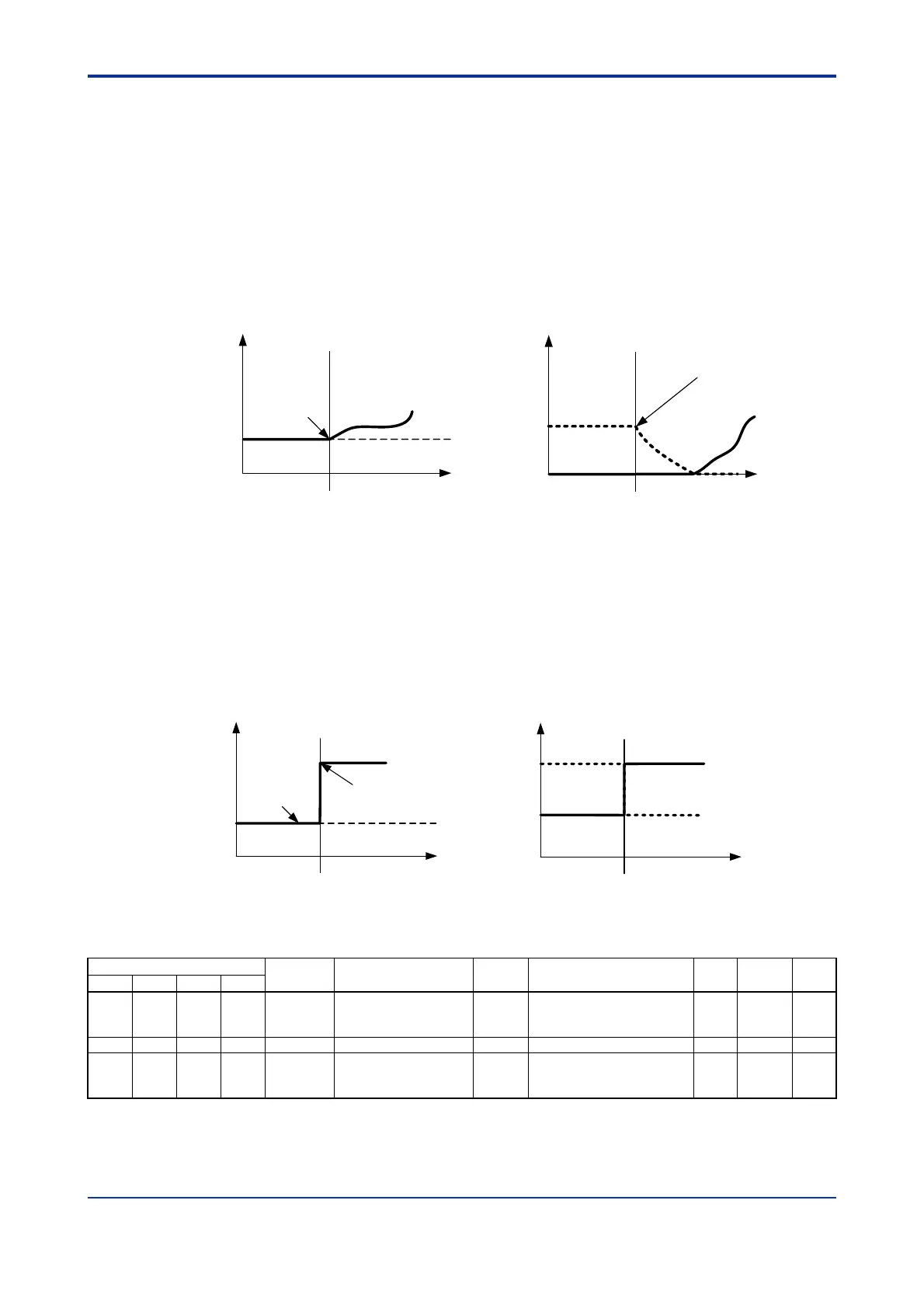
When OT = “0: PID Control” or OT = “2: Heating/Cooling PID Control”:
The switch is “bump-less” on the control output value. Control and computation begins
with the output value immediately after the switch as the origin (if Integral Time (TI) is set
to “0: OFF”, the control output bumps to the new value).
MOUT
Control output
Time
Switching from Manual to Automatic
Control and
computation
begins from
MOUT
(1) Switching from Manual to Automatic
in PID Control
Control output
Time
Switching from Manual to Automatic
Control and
computation
begins
(2) Switching from Manual to Automatic in
Heating/Cooling PID Control
0%
MOUT
MOUTC
Figure C7.7 Switching to Automatic Mode in PID Control or Heating/Cooling PID Control
When OT = “1: On/Off Control” or OT = “3: Heating/Cooling On/Off Control”:
The control output value is determined by the PV and CSP values, independent of the
control output value in Manual mode.
OFF
MOUT
Control output
Time
Switching from Manual to Automatic
Turns on because
PV < CSP
(1) Switching from Manual to Automatic in
On/Off Control (when PV < CSP)
ON
OFF
Control output
Time
Switching from Manual to Automatic
(2) Switching from Manual to Automatic
in Heating/Cooling On/Off Control
(when DB = 0 and PV < CSP)
ON
HOUT
COUT
MOUT
MOUTC
Figure C7.8 Switching to Automatic Mode in PID Control or Heating/Cooling PID Control
Table C7.4 Parameters Related to Automatic/Manual Switching
Data Position Number
Symbol Description Unit Data Range
Default
Value
Attribute
Stored
Loop1 Loop2 Loop3 Loop4
134 334 534 734 MOUT Manual output %
OL to OH: for single output
0 to OH: for heating/cooling
output
0 RW —
135 335 535 735 MOUTC Manual Cooling output % 0 to OL 0 RW —
122 322 522 722 A/M/C
Automatic/Manual/
Cascade Selection
None
0: Automatic
1: Manual
2: Cascade
*1
0 RW —
*1 The controller mode must be set to Cascade Control before Automatic/Manual/Cascade Selection (A/M/C) can be
set to 2 (Cascade). In cascade control, operation proceeds according to the setup for the even-numbered loop (loop 2
or 4).
 Loading...