C7-7
IM 34M06H62-02E 2nd Edition : June 2008-00
C7.4 Automatic/Manual/Cascade Switch
Automatic/Manual/Cascade switching is enabled only in cascade control. Setting is
performed using the Automatic/Manual/Cascade Selection (A/M/C) parameter of the
even-numbered loop.
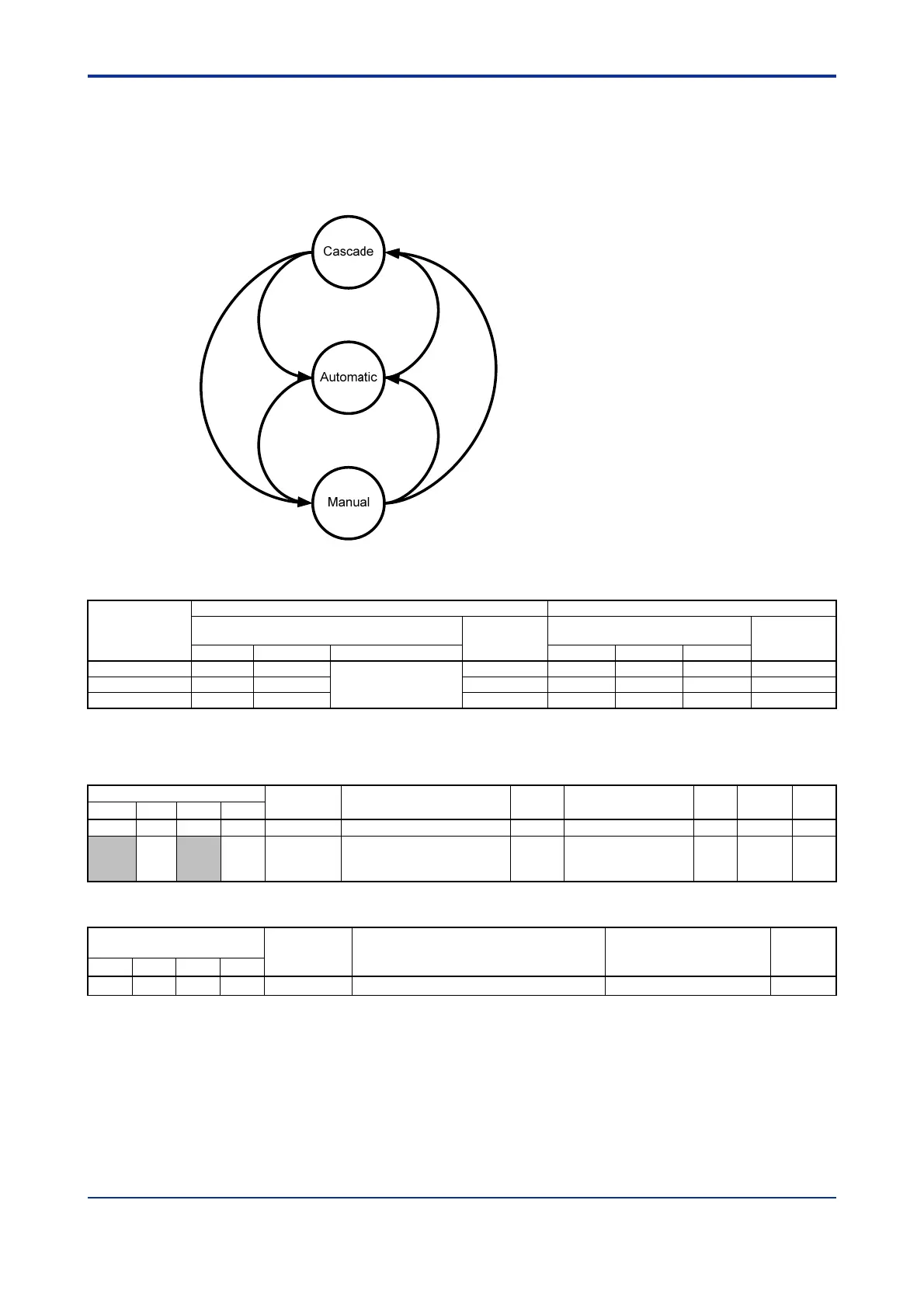
Figure C7.10 shows the mode transition diagram.
Figure C7.10 Switching Modes
Table C7.6 Operating Status and Input Relays in Cascade Control
A/M/C
(even-numbered
loop)
Odd-numbered Loop
Even-numbered Loop
RUN.STUS
Input Register
A/M
Input Relay
*1
RUN.STUS
Input Register
A/M
Input Relay
*1
CAS AUT/MAN RMT/LOC
CAS
UT/MAN RMT/LOC
0: Automatic 0 0
Same as RMT/LOC
I/O register of the
odd-numbered loop
0 0 0 0 0
1: Manual 0 1 0 0 1 0 1
2: Cascade 1 0 1 1 0 1 0
*1 By reading the A/M input relay for both the odd-numbered and even-numbered loops, you can determine whether a
loop is in automatic, manual or cascade mode.
Table C7.7 Parameters Related to Cascade Mode Switching
Data Position Number
Symbol Description Unit Data Range
Default
Value
Attribute
Stored
Loop1 Loop2 Loop3 Loop4
108 308 508 708 RUN.STUS Operating Status None See Table B2.13 — RO —
322
722 A/M/C
Automatic/Manual/Cascade
Selection
None
0: Automatic
1: Manual
2: Cascade
0 RW —
Table C7.8 Input Relays Related to Cascade Mode Switching
Input Relay Number
Xnn
*1
Symbol Description Data Range Interrupt
Loop1 Loop2 Loop3 Loop4
X03 X11 X19 X27 A/M Automatic/Manual 0: Automatic; 1: Manual —
*1 denotes the slot number where the module is installed.
 Loading...