B2-20
IM 34M06H62-02E 2nd Edition : June 2008-00
B2.3 How to Enable Settings
Parameters described in Section B2.2.7, “controller Parameters,” and Section B2.2.10,
“I/O Parameters,” must be enabled before their settings can take effect. This section
describes how to enable various settings and check for successful completion.
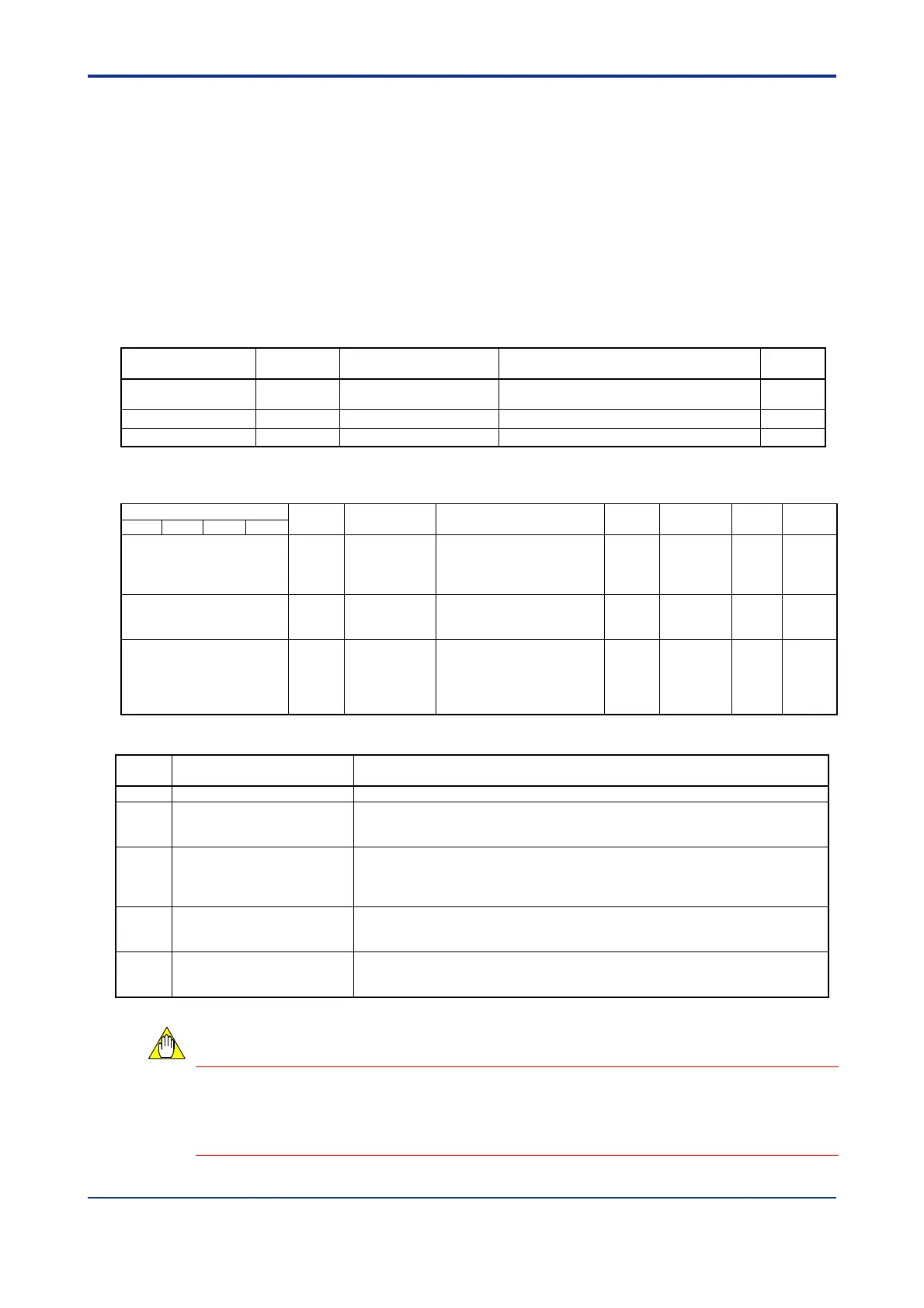
Table B2.25 lists the input relays and Table B2.26 lists the I/O data registers that are used
for enabling controller parameters and I/O parameters.
Write '1: Enable setup instruction operand' to SETUP. Next, write the required parameter
values and then enable them by writing the appropriate setup instruction operand value
to OPE. If the parameters fail to be enabled, a non-zero value is returned in STUS,
indicating an error. Correct the error and retry. After confirming that there is no error, end
the procedure by setting SETUP to '0: Disable setup instruction operand'.
Table B2.25 Relays for Enabling Settings
Input Relay Number
Xnn
*1
Symbol Description Data Range Interrupt
X08 CMDRDY
Command processing
completed
0: Processing, 1: Processing completed
X16 MDLRDY Module startup completed 0: Processing, 1: Processing completed
X24 SETUP.R Setup mode 0: Normal state, 1: Setup mode
*1 denotes the slot number where the module is installed.
Table B2.26 Data Registers for Enabling Settings
Data Position Number
Symbol Description Data Range
Default
Value
Attribute Stored
See
Also
Loop 1
Loop 2 Loop 3 Loop 4
71 SETUP Setup
0: Disable setup instruction
operand
1: Enable setup instruction
operand
0 RW — —
72 OPE
Setup
Instruction
Operand
1, 2, 4, 8, 16: See Table
B2.27 for details.
0 RW — —
73 STUS
Setup
Instruction
Response
0: No error;
Data position number of error
register
-32767: Invalid operation
(SETUP = 0)
0 RO — —
Table B2.27 Setup Instruction Operand (OPE) Values
Preset
Value
Description Explanation
1 Initialize all parameters Reverts all parameters to their factory settings.
1
2 Enable controller parameters
Enables the controller parameters, which are the most basic setup elements.
The module initializes I/O parameters and operation parameters based on the
controller parameter values.
4 Enable I/O type settings
Enables the I/O Type Selection parameter, which defines the input type and control
output type.
The module initializes input range settings, PV range settings and Operation
parameters based on the input type selection parameter value.
8 Enable input range settings
Enables the input range settings, which sets up the PV as required.
The module initializes PV range settings and operation parameters based on these
settings.
16 Enable PV range settings
Enables the PV range settings, which are required only in Two-input Changeover
mode.
The module initializes operation parameters based on these settings.
*1 Input type and power frequency selection defined by the hardware switches have precedence over software settings.
Writing to the Setup Instruction Operand (OPE) register a value, which is not listed in
Table B2.27, “Setup Instruction Operand (OPE) Values,” has no effect on module
operation. When the setup operation completes, the Setup Instruction Operand (OPE)
register resets to 0.
CAUTION
 Loading...