C3-10
IM 34M06H62-02E 2nd Edition : June 2008-00
C3.5 Burnout Detection
Burnout detection checks for an open circuit on an input.
For thermocouple or RTD input, you may define a burnout condition by specifying the
direction of change in the input value and the final input value. For DC voltage input,
burnout detection is not available.
When an open-circuit occurs with the Burnout Selection (BSL) parameter set to ‘Up-Scale’,
the input value rises to a final value of 105% of the input range (or the PV range in
Two-input Changeover mode).
When an open-circuit occurs with Burnout Selection (BSL) set to ‘Down-Scale’, the input
value drops to a final value of -5.0% of the input range (or the PV range in Two-input
Changeover mode).
If Burnout Selection (BSL) is set to ‘OFF’, the input value is undefined when an open circuit
occurs, and may reach the upper or lower limit, but even if this happens, the FUNC.ERR
relay and the corresponding bit of the RUN.STUS register are not set.
If an open circuit is detected in Run and Automatic operating status, the preset output
value is output as the control output, and the operation of the alarm depends on the input
value at that moment.
If an open circuit is detected in Run and Manual operating status, the manual output value
is output as if no open circuit has occurred.
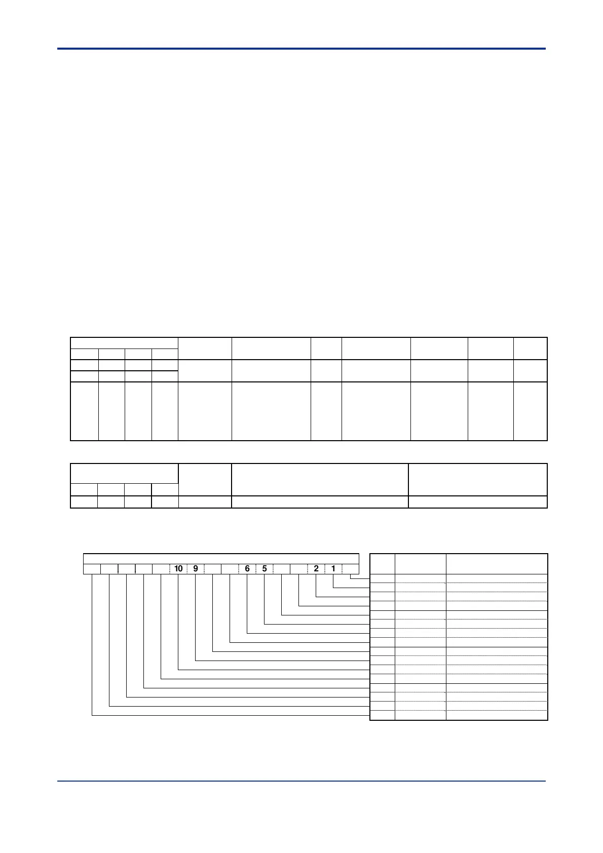
Table C3.7 Burnout-related Parameters
Data Position Number
Symbol Description Unit Data Range Default Value Attribute Stored
Loop 1 Loop 2
Loop 3
Loop 4
41 42 43 44
RUN.STUS Operating status None
On/off for
individual bits.
— RO —
108 308 508 708
150 350 550 750 BSL Burnout selection None
0: OFF
1: Up-scale
2: Down-scale
(valid only for
thermocouple and
RTD input)
1 RW
Table C3.8 Burnout Detection Relay
Input Relay Number
Xnn
*1
Symbol Description Data Range
Loop 1
Loop 2
Loop 3
Loop 4
07 15 23 31 FUNC.ERR Burnout or other error detected
2
0: Normal, 1: Error
*1: denotes the slot number where the module is installed.
*2: Notifies that a burnout has been detected, or that self-diagnosis has detected an AD converter error or some other error
that affects normal module operation.
Table C3.9 Operating Status
RUN.STUS
Bit
Pos.
Symbol Description
1
14 1
12 11 10
4
210
0RUN/STP 0: Sto
1: Run
1AUT/MAN 0:
utomatic
1: Manual
CAS 1: Cascade mode
3RMT/LOC 0: Local
1: Remote
4 EXPV/PV 0: Normal
1: External in
ut
EXOUT/OUT 0: Normal
1: External out
ut
6 ―
7 ―
B.OUT 1: PVIN burnout
9+OVER 1: PVIN +OVER
10 -OVER 1: PVIN -OVER
11 B.OUT 1: PV burnout
1
+OVER 1: PV +OVER
13 -OVER 1: PV -OVER
14 ―
1
FUNC.ERR 1: Error detected
A PVIN burnout always reflects the input condition of the corresponding loop.
A PV burnout in Single Loop control is equivalent to a PVIN burnout.
A PV burnout detected on an even loop in two-input changeover control may mean an
actual burnout on either the even loop or the odd loop of the pair of loops.
 Loading...