C1-7
IM 34M06H62-02E 2nd Edition : June 2008-00
Performing PID Adjustment in Cascade Control
Use the following procedure to perform auto-tuning or manual PID adjustment:
(1) Perform auto-tuning or manual PID adjustment in automatic mode to determine
optimal PID values for the secondary loop.
(2) Switch to cascade control mode, and perform auto-tuning or manual PID
adjustment for the primary loop to determine optimal PID values.
- Changing the Automatic/Manual/Cascade Selection (A/M/C) of the secondary loop
from Automatic to Cascade or Manual during auto-tuning stops auto-tuning.
- Changing the Automatic/Manual/Cascade Selecton (A/M/C) of the primary loop from
Cascade to Automatic or Manual during auto-tuning stops auto-tuning.
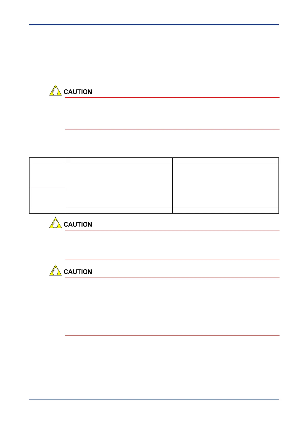
Functional Limitations in Cascade Control
Table C1.6 Functional Limitations in Cascade Control
Set Point Function
Output-related Functions
Primary Loop
The PV tracking operation interlocks with the Run/Stop
Selection and the Automatic/Manual/Cascade
Selection specified for the secondary loop.
Control Type Selection is disabled (PID Control is
always used).
In automatic or manual mode, the control output of the
primary loop follows the control set point of the
secondary loop (tracking function).
Secondary Loop
In cascade control mode, the control output from the
primary loop is used as the control set point for the
secondary loop. The Remote/Local Selection is
disabled (Local is always selected).
No limitations
See Also C4, “SP-related Functions” C2, “Output-related Functions”
To stabilize the control output from the secondary loop in situations where the output from
the primary loop changes drastically, set the control mode (CMD) of the secondary loop
to “Fixed-point Control”. For details on the PID control mode, see Section C6.6, “PID
Control Mode.”
In cascade control mode, the control set point for the secondary loop is constrained by
the upper and lower output limits (n.OH and n.OL) of the primary loop, as well as the
upper and lower SP limits (n.SPH and n.SPL) of the secondary loop.
The specified upper and lower SP limits (n.SPH and n.SPL) of the secondary loop must
be appropriate for the upper and lower output limits (n. OH and n. OL) of the primary loop
respectively. If the two values do not fit, the output of the secondary loop may overshoot
significantly. For details, see the CAUTION in Section C4.3, “Limiting the Set Point.”
Note: “n.” in the parameter symbol denotes a PID number, which is an integer ranging from 1 to 4.
 Loading...