B3-4
IM 34M06H62-02E 2nd Edition : June 2008-00
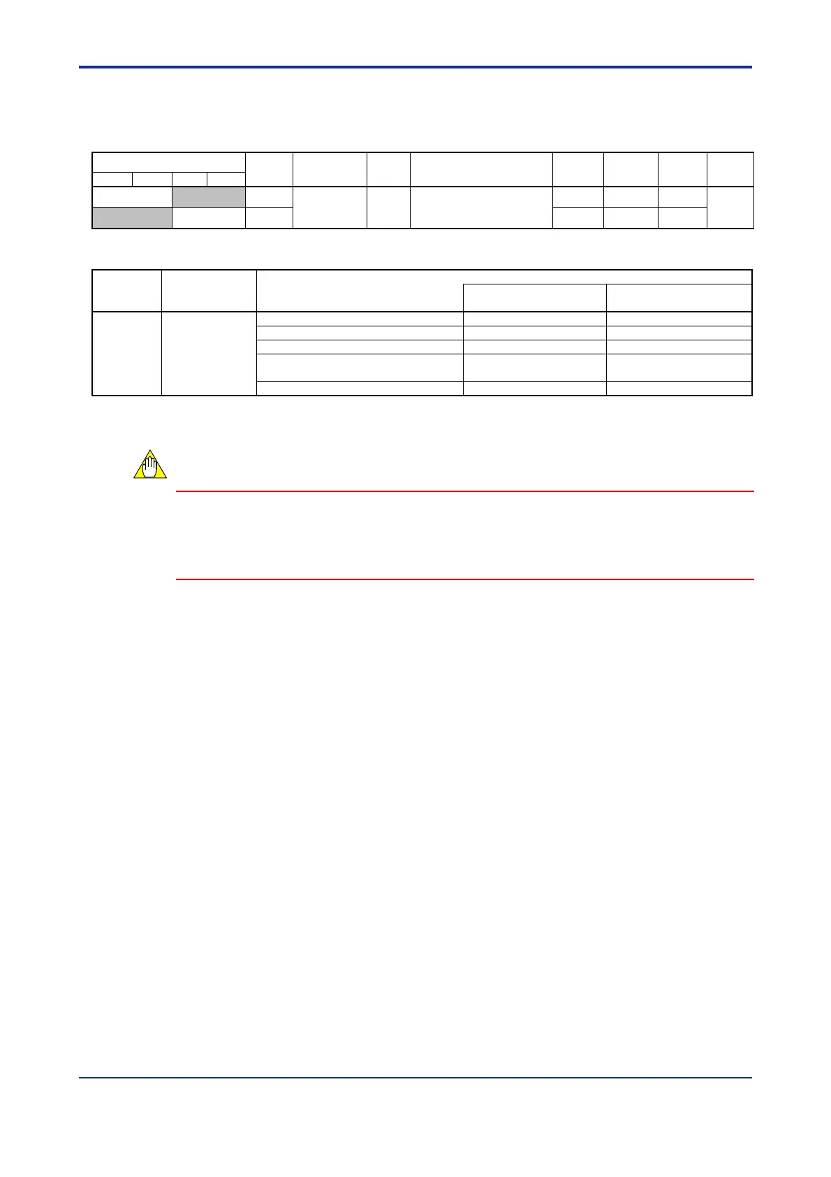
The controller mode is configured for a pair of loops. Register MD12 corresponds to
loops 1 and 2, whilst MD34 corresponds to loops 3 and 4. Table B3.5 shows the mapping
between controller mode preset values and loops.
Table B3.4 Controller Mode
Data Position Number
Symbol Description
Unit Data Range
Default
Value
Attribute Stored
See
Also
Loop 1 Loop 2 Loop 3
Loop 4
83 MD12
Controller
mode
None
0 to 4: See Table B3.5 for
details.
0 RW
C1
84 MD34 0 RW
Table B3.5 Controller Mode and Loops
Symbol Description
Relationship
between Controller Mode Preset Value and Loop
Odd-numbered Loop
(Loop 1 or 3)
Even-numbered Loop
(Loop
2 or 4)
MD12
MD34
Controller
mode
0: Two single loops Single loop Single loop
1: Two-input changeover control Low temperature input
High temperature input
2: Cascade control Primary loop Secondary loop
3: Single loop
(Odd-numbered loop is disabled)
Not used Single loop
4: Both loops disabled Not used Not used
*1: Only the input function of the loop is used.
Controller Mode is a controller parameter. Changing a controller parameter reverts all
parameters of the module to their default values.
However, switching between the Disabled and Single Loop modes, that is, between
controller modes 0, 3 and 4 will not initialize the parameters.
CAUTION
 Loading...