4-13
IM 04L20A01-01E
Measurement Input and Alarm Setup Operations
4
Pulse Input Measurement Example
Pulses are counted and displayed using computation channels. This is a description of
the settings for the application example below. For the setting procedure of the
computation channels, see section 8.1. For a description on computation function, see
section 1.6.
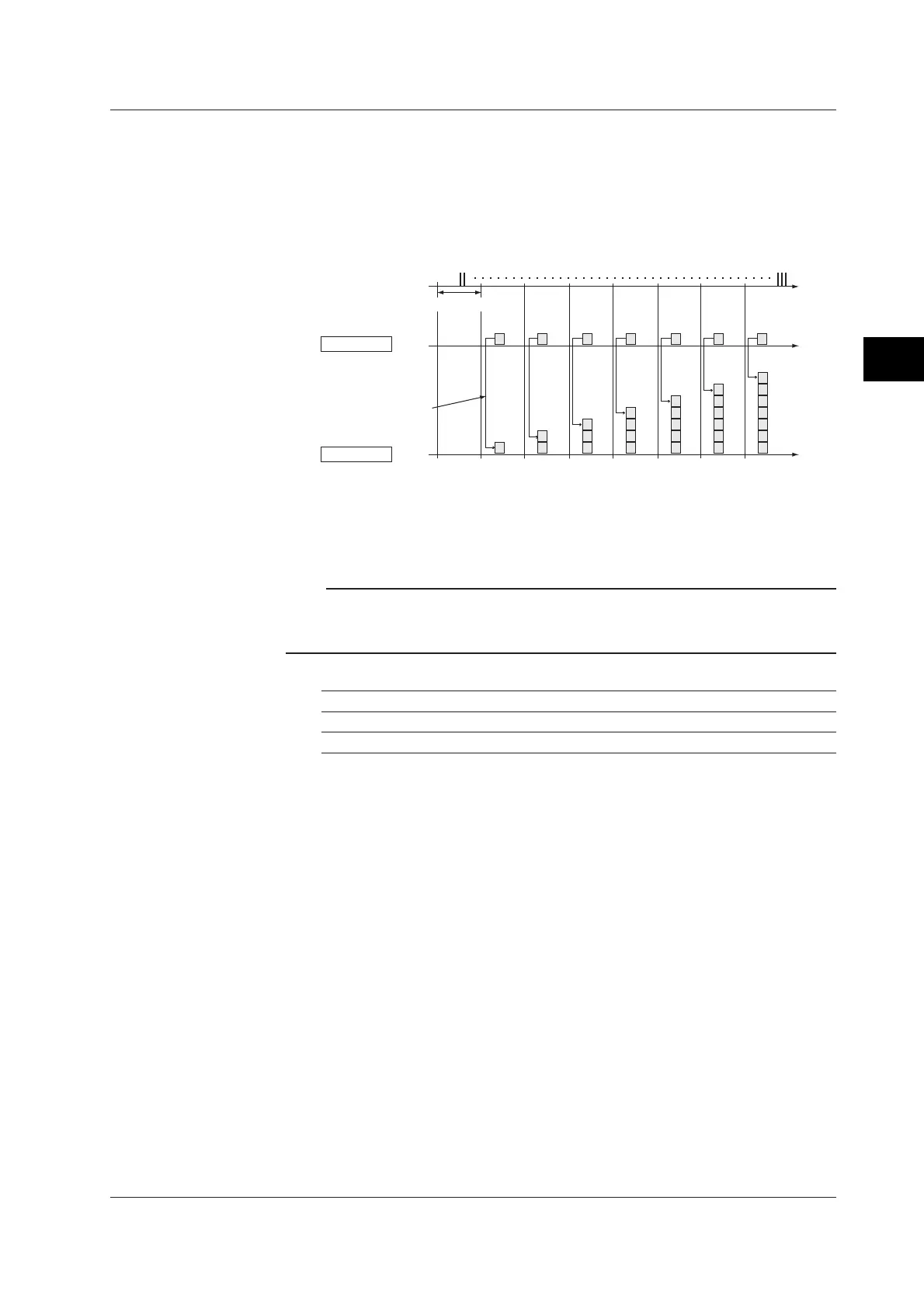
Application Example 1: Pulse Sum Value
The pulses input through the terminal 6 is summed and displayed.
Ch 31
Number of pulses
per scan interval
Ch 33
Pulse sum value
Pulse input
Time
(Sum)
Scan interval
•
• Computation equation
Assign computation channels as follows. Set computation equations for each
channel. Upper/lower limit of span is set according to the application.
Note
In a single measurement interval, calculation is performed on numbered channels in the order
from smallest to largest. For channels that calculate sum values, use higher-numbered
channels than those of the channels that count the number of pulses at each scan interval.
Channel Equation Description
31 D6 Counts the number of pulses every scan interval.
33 TLOG.SUM(31) Pulse sum value
• Channel 31
Equation: D6
D6 indicates the counting of pulses on pulse input terminal 6. The number of pulses
per scan interval is counted and displayed.
• Channel 33
Equation: TLOG.SUM(31)
The sum value of the pulses counted on channel 31 is calculated using the
TLOG.SUM function, and displayed. See page 1-44 for information about
TLOG.SUM.
4.3 Setting Pulse Input (/PM1 Option)
 Loading...


