2.HardwareSpecications
2-1
TI 30A10A30-01E
2. HardwareSpecifications
2.1 RS40 Family
9ports,DINrailmountingmodel
GRVSW-660FA (Vender model name: RS40-0009CCCCEDBPYY): L2SW, DC x 2
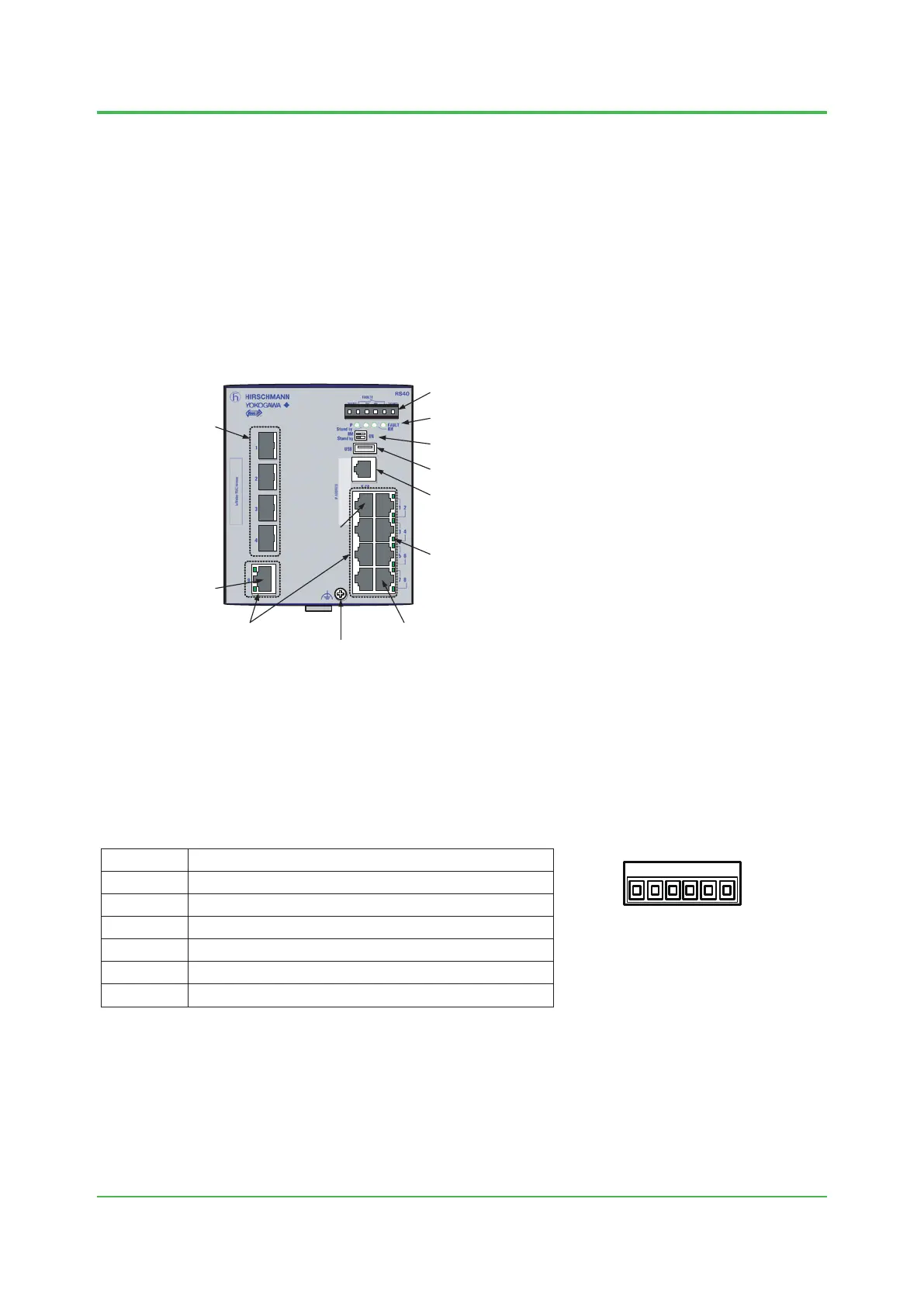
2.1.1 NameofEachPartandDescriptions
F020101.ai
Power Input/FAULT output
Device status LEDs
DIP switch
USB interface
V.24 interface
Port status LED
Port 8
Port 1
Port 9
RJ-45 port
Grounding Screw
SFP port
Figure NameofEachPart(RS40Family)
Powerinput/FAULToutput
A 6-pin plug-in terminal block is installed to this connecter.
The terminal pin functions are as shown below.
Table TerminalPinFunction(RS40Family)
Pin Function
1 P1 DC power input (+)
2 FAULT output
3 P1 DC power input (-)
4 P2 DC power input (-)
5 FAULT output
6 P2 DC power input (+)
Sep. 19, 2014-00
F020104.ai
1 2 3 4 5 6
Ensure to connect 24 V DC power cable with the correct polarity.
This family of switches has redundant power supplies. Use both P1 and P2 power inputs unless
otherwise the power fail alarm will be set off on the device.
In case the device detects status error, two FAULT output pins will become open. The device
status error is triggered by power failure in the default configuration.
For more information about wiring to the terminal block, see section 2.4.2.
Figure Terminal Pins
 Loading...