2.HardwareSpecications
2-3
TI 30A10A30-01E
Shielding ground
The front panel of the device is grounded via this ground screw.
For the ground conductor, use a cable with a cross section of at least 1.0 mm
2
.
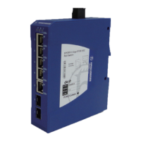
2.1.2 Mounting
RS40 family device of the Recommended Switch is designed for mounting onto a 35 mm DIN rail
as shown in the figure below.
Attach the device’s upper snap-in guide into the DIN rail and press it down against the DIN rail
until it snaps into place.
F020102.ai
Figure MountingontheDINrail(RS40Family)
To take the RS40 family device off the DIN rail, insert a screwdriver horizontally under the
housing into the locking slide, pull it (without tipping the screw driver) downwards and lift the
device upwards.
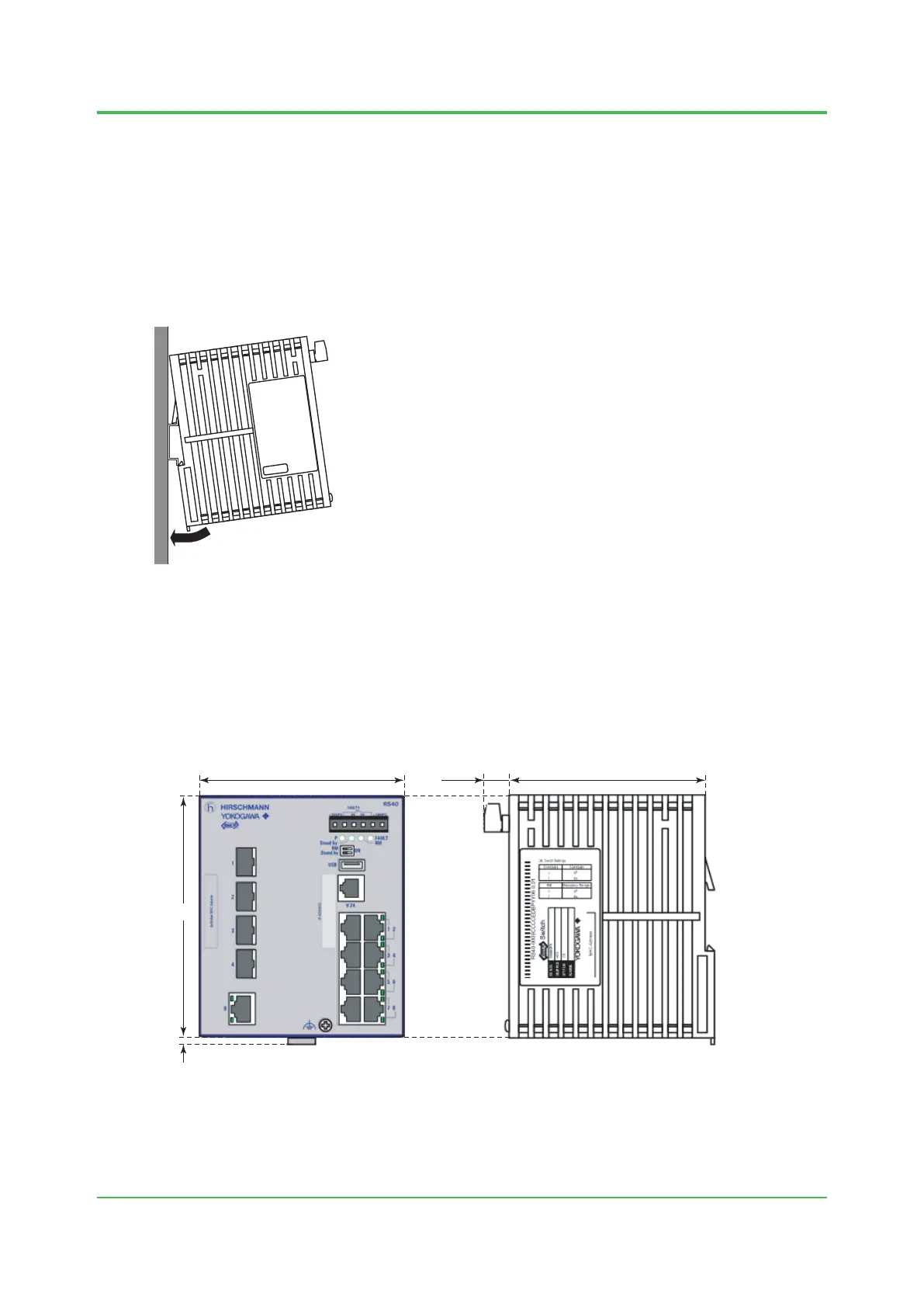
2.1.3 ExternalDimensions
F020103.ai
105.313.73110.0
3.5
130.0
Unit: mm
Figure ExternalDimensions(RS40Family)
Dec. 26, 2016-00
 Loading...