1-6
IM 04L51B01-17EN
1.2.4 RS-422/485 Connection Procedure
Connect a cable to the terminal.
Connection
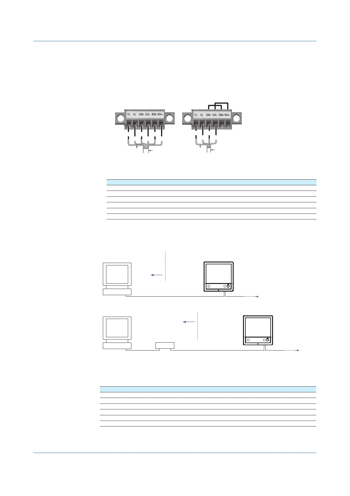
• Connecting the Cable
As shown in the figure below, remove approximately 6 mm of the covering from the end of
the cable to expose the conductor. Keep the exposed section from the end of the shield
within 5 cm.
Two-wire systemFour-wire system
Electric potential
of the shield
Shield
FG SDB+
SG SDA−
Electric potential
of the shield
Shield
FG SDB+
SG SDA−
RDB+
RDA−
Recommended torque
for tightening the screw: 0.2 N•m
• Signal names
Each terminal corresponds to the signal indicated below.
Signal Name Meaning
FG Frame ground of the recorder.
SG Signal ground.
SDB+ Send data B (+).
SDA– Send data A (–).
RDB+ Receive data B (+).
RDA– Receive data A (–).
Connecting to the host device
The figure below illustrates the connection of the recorder to a host device. If the port on the
host device is an RS-232 interface, connect a converter.
terminal on the recorder
Host computer
or host device
Host device side
Converter
RS-422/485
RS-422/485
terminal on the recorder
Host computer
RS-232
RS-422/485
Host device side
Connection example to the host device
A connection can be made with a host device having a RS-232, RS422, or RS-485 port. In
the case of RS-232, a converter is used. See the connection examples below for a typical
converter terminal. For details, see the manual that comes with the converter.
RS-422/485 Port Converter
SDA(–) TD(–)
SDB(+) TD(+)
RDA(–) RD(–)
RDB(+) RD(+)
SG SHIELD
FG EARTH
There is no problem of connecting a 220-Ω terminator at either end if YOKOGAWA’s PLCs
or temperature controllers are also connected to the communication line.
1.2 Operations over the Serial Interface (RS-232, RS-422/485, USB, Bluetooth)
 Loading...
