1-3
IM 04L51B01-17EN
Using Dedicated Commands (General)
1
1.2.3 RS-232 Connection Procedure (GX/GP)
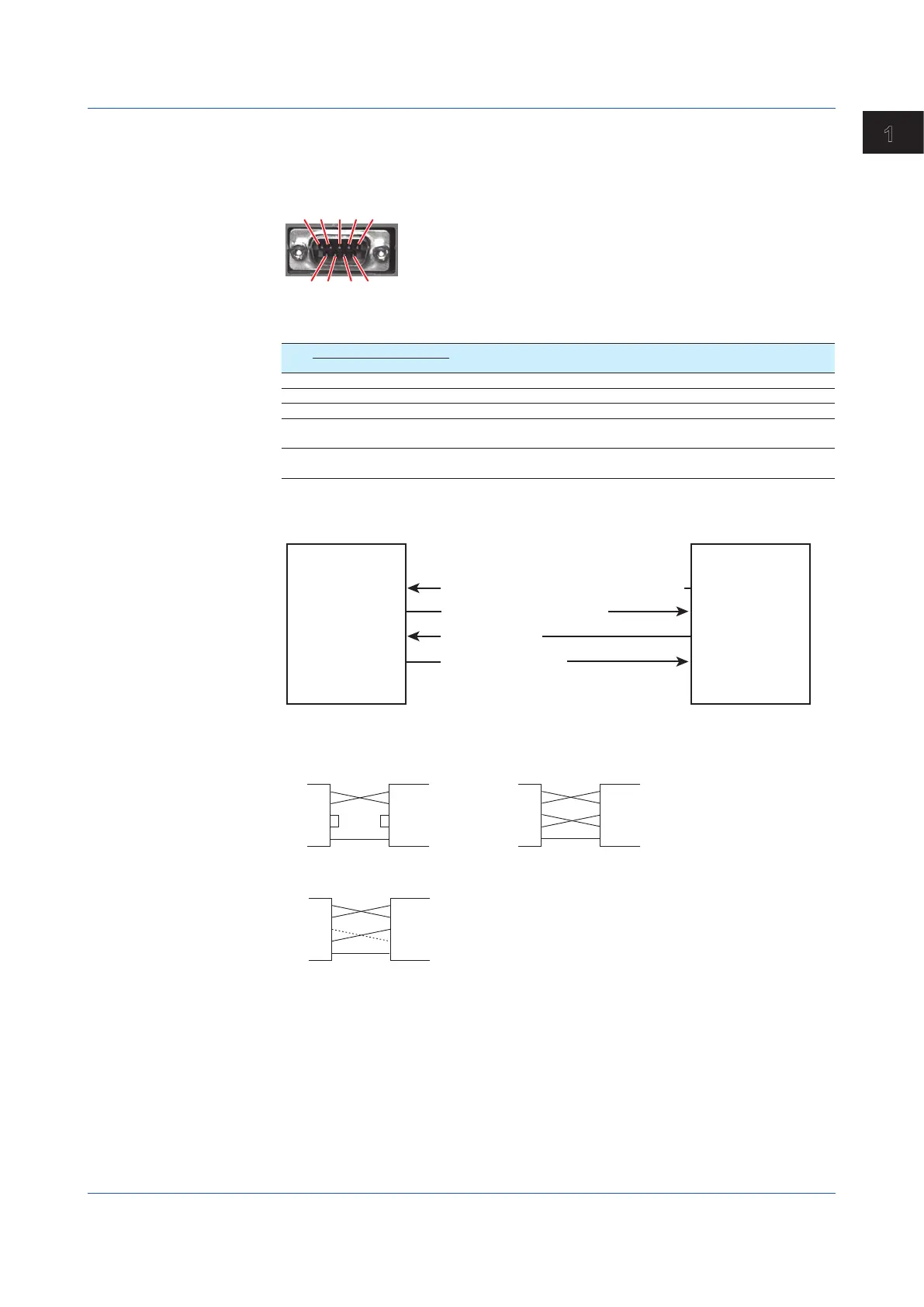
Connect a cable to the 9-pin D-sub RS-232 connector.
Connection
• Connector pin arrangement and signal names
Each pin corresponds to the signal indicated below. The following table shows the signal
name, RS-232 standard, JIS, and ITU-T standard signals.
Pin
1
Signal Name Name Meaning
JIS ITU-T RS-232
2 RD 104 BB(RXD) Received data Input signal to the GX/GP.
3 SD 103 BA(TXD) Transmitted data Output signal from the GX/GP.
5 SG 102 AB(GND) Signal ground Signal ground.
7 RS 105 CA(RTS) Request to send Handshaking signal when receiving data from the
PC. Output signal from the GX/GP.
8 CS 106 CB(CTS) Clear to send Handshaking signal when receiving data from the
PC. Input signal to the GX/GP.
1 Pins 1, 4, 6, and 9 are not used.
• Signal direction
PC GX/GP
RS [Request to send...Ready to receive]
SD [Send data]
RD [Received data]
2
3
8
7
CS [Clear to send...Ready]
• Connection example
SD
RD
RS
CS
SG
SD
RD
RS
SG
PC GX/GP
SD
RD
RS
CS
SG
SD
RD
RS
SG
• XON-RS(XON-RTS)
PC GX/GP
SD
RD
RS
CS
SG
SD
RD
RS
SG
PC GX/GP
CS
CS
CS
2
3
8
7
5
2
3
8
7
5
2
3
8
7
5
The connection of RS on the PC and CS
on the GX/GP is not necessary. However,
we recommend that you wire them so that
the cable can be used in either direction.
1.2 Operations over the Serial Interface (RS-232, RS-422/485, USB, Bluetooth)
 Loading...
