<2. Installation>
2-1
IM 12B07W01-04EN 1st Edition : Nov. 11, 2016-00
2. Installation
The chemical cleaning pH measuring system can be installed indoor/outdoors. Choose an
appropriate location (free from dust, sunlight, rain) for easy maintenance. Note that since the
system uses water for washing and a chemical solution, care must be taken to ensure that these
liquids are protected from freezing in winter.
Note: Install the PH201G distributor, which is required when using the 2-Wire Analyzer, in an
indoor location such as an instrument room.
This chapter explains the procedure for installing the component equipment, highlighting the
PH8SM3 Chemical Cleaning Unit for the chemical cleaning system and the PH8HS3 holder.
2.1 Installing the PH8SM3 Chemical Cleaning
Unit for a Chemical Cleaning System
2.1.1 Where to install the unit
Install the PH8SM3 operating unit for a chemical cleaning system in a location which meets the
following requirements.
(1) Close to the pH measurement point (location where the PH8HS3 holder is installed)
The operating unit for the chemical cleaning system and the holder are connected via
electrical wiring as well as the piping through which the chemical solution is supplied. Keep
the length of the tubing for supplying the chemical solution to a minimum (less than 10 m) in
order to reduce piping resistance.
(2) The maximum tube length between the cleaning unit and the sensor holder is 10 m.
It is preferable to install the stand at the same level as the sensor holder. If this is impossible,
the stand can be installed a maximum of 2 m below the holder level. Installation above the
holder level causes no problem.
(3) Easy access for maintenance work
The location must allow users to have an easy view of the display on the PH450G pH/ORP
Converter or 2-wire Analyzer FLXA202/FLXA21, and to operate the control box with ease
to set the pressure. Also, consider the ease of work required when relling the holding tank
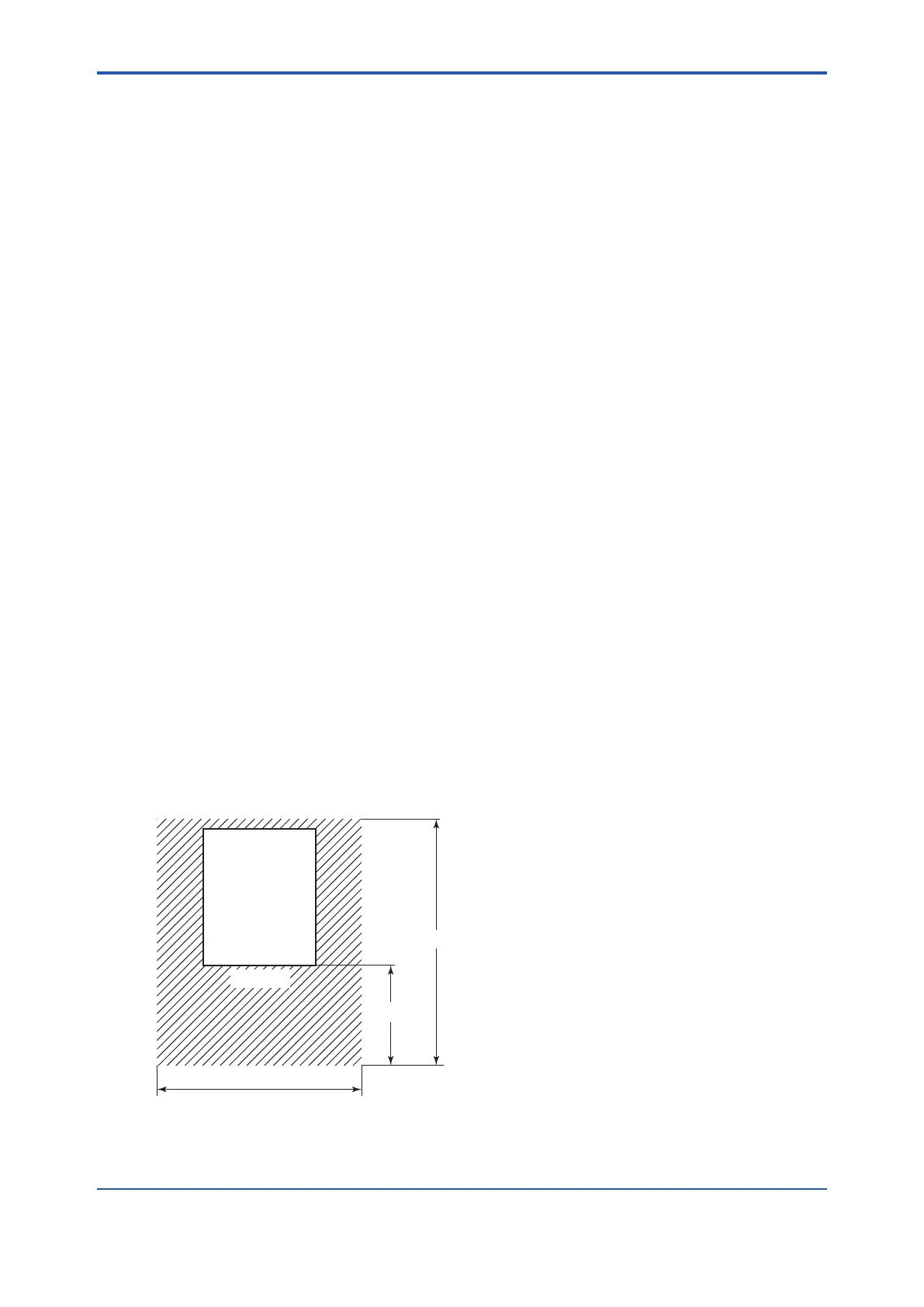
with the chemical solution. Furthermore, secure the clearance for maintenance access
shown in Figure 2.1.
PH8SM3
F2.1.ai
Unit: mm
Front view
Approx. 1150
Approx. 500
More than 900
Figure 2.1 Clearance for Maintenance Access
 Loading...


