<4. Operation>
4-7
IM 12B07W01-04EN 1st Edition : Nov. 11, 2016-00
4.3.5 Setting Duration of Forced Feeding of Chemical
Solution and Output of CYLINDER FAIL Signal
The timers in the control box are used to set the time for forced feeding of the chemical solution
and output of the CYLINDER FAIL signal. Use timer T2 (setting range: 0 to 10 minutes) to set the
time for forced feeding of the chemical solution; use timer T1 (setting range: 0 to 2 minutes) to set
the time for output of the CYLINDER FAIL signal.
Note: The adjustment screw on timer T1 is hidden under the terminal cover.
Upon shipment, the time for forced feeding length of the chemical solution is set to approximately
two minutes. Similarly, the time for output of the CYLINDER FAIL signal is set to approximately
30 seconds. Conrm these settings and change them, if necessary.
Note: Always make sure that the value set on timer T2 for forced feeding length of the chemical
solution is smaller than that for the WASH time (output of the WASH contact signal).
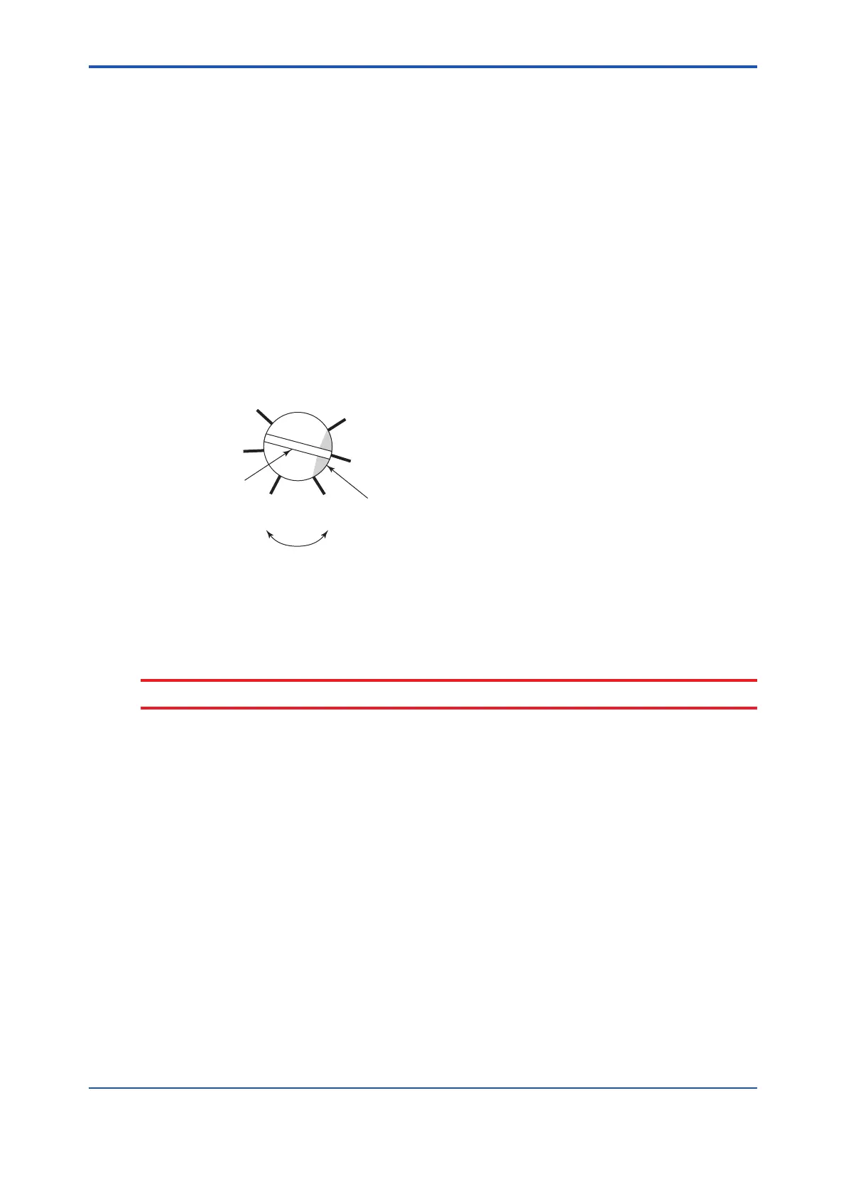
Note: that both of these timers have graduations which divide an angle of approximately 270°
(corresponding to the setting range) into ve identical segments as shown in Figure 4.6. Use
a at-blade screwdriver to rotate the adjustment screw so the end of the slot on the screw
head (on the side painted in white) points to the desired time setting.
S
L
F4.6.ai
Slot on the head of
the adjustment screw
More time Less time
Turn the screw to the side
painted in white is set at the
desired time setting.
Figure 4.6 Graduations on Timer
When completing the verication and resetting of timer settings, close the door on the control
box. The interior of the control box is air purged. Keep the door closed as much as possible.
CAUTION
Conrm that the MANUAL WASH switch inside of the control box is OFF.
4.3.6 Supplying Power
Turn on power to the chemical cleaning pH measuring system.
pH/ORP converter system has the power on switch installed on the power line to the power
supply box of Chemical Cleaning pH measuring unit. Startup the entire system can be put into
operation simply by turning on this switch. If your system is the 2-Wire Analyzer system, turn on
the switch installed on the power line to the control box and turn on the power to the distributor.
4.3.7 Entering Data Related to WASH Operation
Parameters related to WASH operation include, besides the data items discussed in Subsection
4.3.5, the interval between WASHs, WASH time and relaxation interval,
These parameters are set on the PH450G or FLXA202/FLXA21.
Upon shipment, these data settings are provided as shown in Table 4.1. Conrm these settings
before operation and change them as necessary.
For operation required to verify or change these settings, see the instruction manuals of PH450G
or FLXA202/FLXA21.
 Loading...


