<4. Operation>
4-4
IM 12B07W01-04EN 1st Edition : Nov 11, 2016-00
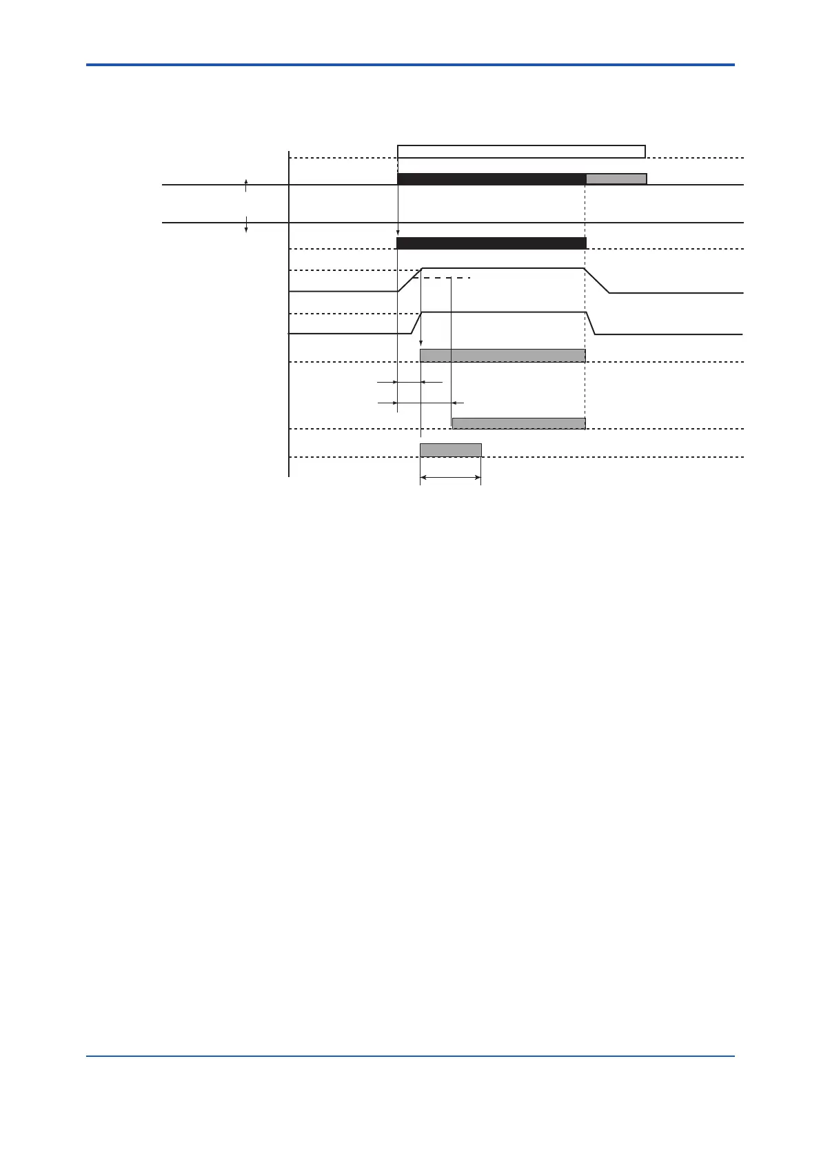
4.2.3 Wash Sequence
Figure 4.4 shows the actions that the system implements to clean the electrodes when
it receives a WASH (cleaning) command from either PH450G or FLXA202/FLXA21.
t2
t1≥
t1<
Holding of pH output signal
WASH
pH meter
Chemical cleaning system
SV2 solenoid valve for
actuating cylinder
Sensor holder
Highest position
Lowest position
Bottom plate of
cleaning chamber
Closes
Opens
DETECT UPPER LIMIT
signal
CYLINDER FAIL signal
SV1 solenoid valve for
forced feeding of chemical
solution and air bubbling
(Measurement mode) (Measurement mode)
(WASH mode)
WASH
Relaxation
Air is injected to raise the cylinder
Open (air is fed to the metering tank.)
t1: Setting of timer T1 t2: Setting of timer T2
When can not reach
the highest position.
Contact signal
for WASH
Figure 4.4 WASH Sequence
l Output of WASH (cleaning) signal
When the setting the interval between WASH (in pH/ORP Converter or 2-Wire Analyzer ) times
out, the system enters the WASH sequence. The WASH signal is then output to the control box
of the operating unit in the chemical cleaning system for the period equivalent to the value set in
the timer.
l Actuation of SV2 solenoid valve
The SV2 solenoid valve in the control box is active while it is receiving the WASH signal. This
causes a pneumatic pressure to be applied to the port that raises the cylinder on the PH8HS3
holder. Consequently, the sensor holder goes up in conjunction with the cylinder slider.
l Output of DETECT UPPER LIMIT signal and CYLINDER FAIL signal
When the sensor holder reaches the upper limit, the bottom plate of the cleaning chamber closes
and the limit switch is turned on. The ON signal from the limit switch then starts timer T2 in the
control box, causing solenoid valve SV1 to be actuated (the valve is opened). Solenoid valve
SV1, when opened, causes a pneumatic pressure to be applied to the interior of the metering
tank, resulting in an approximately 100 ml of the chemical solution being forced into the cleaning
chamber of the holder. The air is kept supplied until timer T2 times out, bubbling the chemical
solution within the cleaning chamber to enhance the cleaning of the pH sensor electrodes.
Note that if the sensor holder does not reach the upper limit when timer T1, which starts at the
same time the WASH signal is output, is timed out, the CYLINDER FAIL signal is given. This
signal stops (the contact opens) when the WASH contact signal is no longer present.
 Loading...


