<4. Operation>
4-3
IM 12B07W01-04EN 1st Edition : Nov. 11, 2016-00
4.2 How the Chemical Cleaning pH Measuring
System Works
4.2.1 Operating Modes
There are two operating modes in the chemical cleaning pH measuring system: the
measurement mode and cleaning mode.
l Measurement mode
The system performs pH measurement. The sensor holder is in its lowest position, submerging
the pH electrodes in the chemical solution.
l WASH (Cleaning)mode
The sensor holder begins rising from its lowest position by way of the wash command, performs
cleaning of the pH electrodes and then goes into the measurement mode again. The cleaning
mode includes the relaxation interval required after the washing sequence. In the wash mode, it
is possible to hold the output signal as a certain value, such as the last value before the WASH
mode starts.
4.2.2 WASH (Cleaning) Command
WASH command in normal operation is issued from the pH/ORP converter or the 2-Wire
analyzers at the intervals set in these instruments. For the pH measuring system for outdoor use,
the WASH command can be issued on demand using a remote contact input. A WASH command
sent from the pH/ORP converter or 2-wire analyzers consists of two time elements, i.e., the
washing time and the relaxation interval.
Chemical cleaning can also be implemented using the MANUAL Wash (cleaning) switch in the
control box. Turning on this switch causes the chemical cleaning pH measuring system to enter
the wash mode; turning off causes the system to exit from the wash sequence. Note that, when
washing is carried out using the MANUAL WASH switch, neither the pH/ORP converter nor the
2-Wire analyzer performs the functions (such as a holding of the output signal) available in the
wash mode.
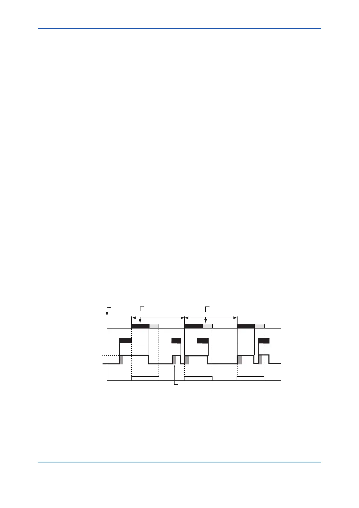
If there is a conict between a WASH command sent from the pH/ORP converter or 2-wire
analyzer and the same command issued with the MANUAL WASH switch in the control box, the
sensor holder behaves according to the timing diagram shown in Figure 4.3.
WASH signal (automatic cleaning)
MANUAL WASH switch on
Sensor holder
Highest position
Lowest position
Holding of pH output signal
Power on
Washing time
Relaxation interval
(WASH mode)
Air for forced feeding of chemical solution
Note:
The interval between wash, washing cycle(time) and relaxation interval are set on the pH/ORP Converter or
2-Wire Analyzer. Hold of the pH output signal is implemented only in the washing sequence
(WASH mode) initiated by a command issued from the pH/ORP converter or 2-Wire Analyzer.
Hold can be off, too. Forced air feeding / Air bubbling of chemical solution continues for a determined length of time ( set in Timer T2) only after
the sensor holder moves from Lowest position to Highest position.
Interval between wash
Interval between wash
pH/ORP Converter or 2-Wire
Analyzer
Figure 4.3 Behaviour of the Sensor Holder If There Is a Conict Between the Automatic-
WASH Command and Manual-WASH Command
 Loading...


