<3. Piping and Wiring>
3-1
IM 12B07W01-04EN 1st Edition : Nov. 11, 2016-00
3. Piping and Wiring
3.1 Piping
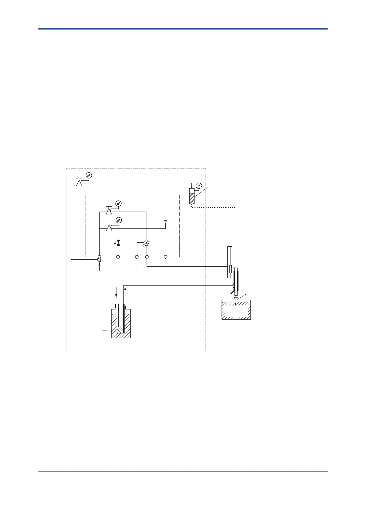
The following lines must be provided to the chemical cleaning pH measuring system.
Lines (2) through (4) are polyethylene resin tubing or joints supplied with the system. Always
make sure that the length of each line is kept to a minimum (less than 10 m).
(1) Line for connecting air source
(2) Line for actuating cylinder to drive sensor pneumatically (upward)
(3) Line for actuating cylinder to drive sensor pneumatically (downward)
(4) Line for forced feeding of chemical solution and air-bubbling
(5) Line for pressurizing KCl reserve tank
Note: If you specify, polyethylene tube or Fluoropolymer (PTFE) tube of 40 m in length come with PH8SM3
with their corresponding tting.
If you do not use the piping materials that came with your system, refer to the notes given in
Subsection 5.1.1. Figure 3.1 shows the pipe lines in the system.
AS1:
AS2:
AS3:
A
F G
B C D E
K
J
H
SV1
SV2
PH8SM3 Operating unit for chemical cleaning system
AS3
AS1
AS2
PG3
PG1
PG2
Pressure reduction valve
for forced feeding of
chemical solution
Pressure reduction valve
foe actuating cylinder
Pressure reduction valve
(optional) for pressurizing
the KCl tank
pH sensor
KCl tank (medium pressure)
(The KCl tank of the pH
sensor is used)
Control box
Dedicated tube
PH8HS3
Holder
Process
liquid bath
Chemical solution
Tank (20 l)
Internal tank
Air
SV2:
SV1:
PG1:
PG2:
PG3:
Pressure gauge
Pressure gauge
Pressure gauge (optional)
2-way solenoid valve
(N, C)
4-way solenoid valve
Purge
A:
B - F:
G - H:
C - J:
D - K:
Rc1/4 or 1/4NPT
Pneumatic line raise
the sensor holder
Pneumatic line to lower
the sensor holder
Pneumatic line
for forced feeding of
chemical solution
<Piping>
Air source connection
Line for forced feeding
of chemical solution
(purge air outlet)
Figure 3.1 Piping Diagram
 Loading...


