<2. Installation>
2-6
IM 12B07W01-04EN 1st Edition : Nov 11, 2016-00
F2.8.ai
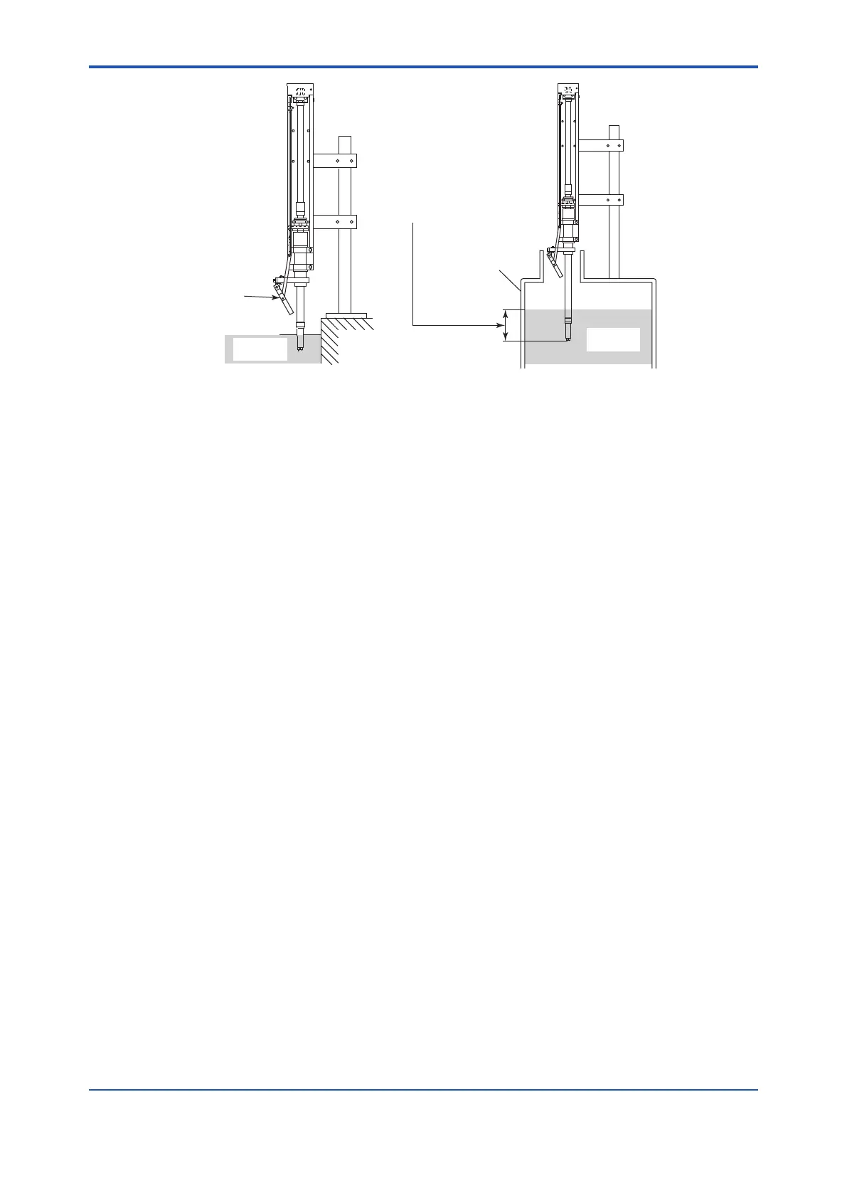
Do not allow the bottom
plate of the cleaning
chamber to become
submerged in the
measured solution.
Measured
solution
Install the holder so the tip of the pH
sensor drops into the measured
solution to a depth of 30 to 90 mm.
Tank
Measured
solution
Figure 2.8 Installed PHSHS3 Holder
l Installing the medium-pressure KCl reserve tank
The KCl reserve tank supplied with the PH8EFP KCl-lling type pH sensor can be installed in the
operating unit for the chemical cleaning system (see Figure 1.1).
Note: Use an appropriate length of KCI supply tube for PH8EFP KCI supply PH sensor.
If installing the KCl reserve tank in other locations, choose a location which is higher than where
the cleaning chamber of the PH8HS3 holder is positioned.
Note This is important to maintain the normal position of liquid junction even when the supply of the pressurizing
air stops.
After completing installation of the KCl reserve tank, connect the KCl supply tube of the pH
sensor to the outlet of the KCI reserve tank.
l Submersion of pH sensor when the measured solution ows fast.
Rapid and continuous ow of measured solution can give the sensor holder distortion, which
hampers the ascent/descent motion of the holder, therefore the result of the measurement may
be affected. Appropriate installation must be guaranteed without distortion of the sensor holder.
If the ow of measured solution gives the sensor holder distortion, install the holder so the tip of
the pH sensor drops in to the solution to a depth of 30 to 90 mm. If this method is not available,
reduce the ow speed so that the distortion never occurs. For the stability of the measurement
result as well, the ow speed must be 2 m/sec or less at a measuring point.
 Loading...


