<4. Operation>
4-6
IM 12B07W01-04EN 1st Edition : Nov 11, 2016-00
F4.5.ai
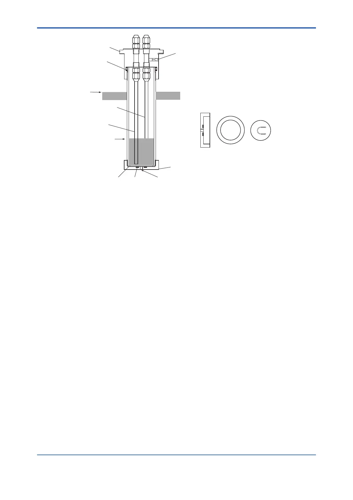
Cap
O-ring
Level of chemical
solution in holding tank
Pressurized Tube (F)
Force-feeding Tube (G)
Level of solution
in metering tank
(Volume: approx. 100 ml)
Gasket
Gasket
(Seat)
Chemical Solution Inlet
Check Valve
Bottom
Bottom
Bleed
Check
Valve
(Seat)
Figure 4.5 Metering Tank for constant quantity of chemical solution
4.3.3 Supplying KCl Solution to Reserve Tank
Fill the KCl reserve tank for the pH sensor with a KCl solution. After lling the tank, follow the
necessary procedures, such as removal of air from inside the sensor unit. Refer to user’s
manual, “PH8EFP KCl Filling type pH Sensor” to do the necessary work.
4.3.4 Adjustment of Pneumatic Pressure
(1) Rotate the knobs on the pressure reduction valves (two) in the control box fully counter
clockwise. Pull the red ring around the knob toward you to turn the knob. If the operating unit
is equipped with an AS3 pressure reduction valve, also rotate the knob on this valve fully
counter clockwise.
(2) Supply air (pressure: 300 to 950 kPa {3 to 9.5 kg/cm
2
}) to the control box. Open the stop
valve located in the line for connecting the air source.
(3) Adjust the pressure of the air for forced feeding of the chemical solution (the air is also used
to purge the interior of the control box). Slowly rotate the knob on pressure reduction valve
AS1 clockwise until pressure gauge PG1 in the control box indicates a reading of 20 to 50
kPa {0.2 to 0.5 kg/cm
2
}.
(4) Adjust the pressure of the air for actuating the cylinder. Slowly rotate the knob on pressure
reduction valve AS2 clockwise until pressure gauge PG2 in the control box indicates a
reading of 300 kPa {3 kg/cm
2
}. A pneumatic pressure is then applied to the “Down” port of
the cylinder in the PH8HS3 holder and forces the sensor holder to move down to the lower
end together with the cylinder slider.
(5) Apply a pneumatic pressure of approximately 10 kPa {0.1 kg/cm
2
} to the KCl reserve tank.
If the PH8HS3 holder is equipped with an AS3 pressure reduction valve, use the valve to do
this. Slowly rotate the knob clockwise while observing the reading of the pressure gauge on
the valve.
 Loading...


