<3. Piping and Wiring>
3-4
IM 12B07W01-04EN 1st Edition : Nov 11, 2016-00
3.2.1 pH/ORP Converter System
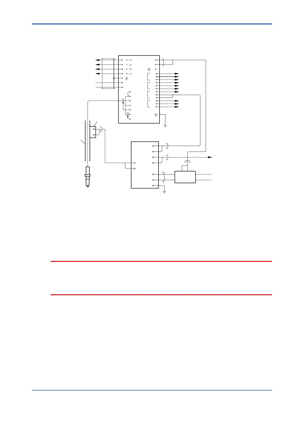
Figure 3.2 illustrates electrical connections for pH/ORP converter system.
Power
supply unit
L1
L2
L1
L2
A1 A2
pH Sensor
wiring by customer
100V AC
PH8SM3
Control Box
Cleaning signal
Ground to earth
Air Cylinder
Cylinder failure signal
pH
Holder
8
9
4
5
6
7
1
2
3
1
2
Position signal
mA1
mA2
CONTACT
IMP.LOW
Jumper
POWER
21
22
13
11
12
14
15
16
(Fail-
safe)
S1
1
2
NC
C
NO
S2
NC
C
NO
S3
NC
C
NO
S4
NC
C
NO
Output signal
(4 to 20 mA DC)
Output signal
(4 to 20 mA DC, HART)
Remote
Contact input
PH450G
Figure 3.2 Wiring for pH/ORP Converter (PH8SM3-E)
(1) Connection for pH sensor cable
Connect the sensor cable so that the code on each core wire matches the corresponding
code on the PH450G pH/ORP Converter. For more information about sensor cable
connection, see the user’s manual “PH450G pH/ORP Converter.” Also refer to “WTB10
Relay Terminal Box” user’s manual if your system uses a relay terminal box.
CAUTION
The sensor cable and the KCI supply tube move up and down in synchronization with the sensor
holder along the PH8HS3 holder. No slack in cable or tube is allowed. Provide an installation
location to ensure that a smooth up-and-down motion takes place. The cable or tube may be
damaged if, during the up-and-down motion, it comes into accidental contact with the PH8HS3
holder or other structures.
(2) Connection for DETECT UPPER LIMIT signal (signal for detecting the upper limit of
sensor holder’s position)
Use a two-core cable with an outer diameter of 9 to 12 mm for this connection. Treat both
ends of each cable core so they t M4 threads. Connect terminal 1 of the terminal block for
the limit switch of the PH8HS3 holder to terminal 8 of the control box, and terminal 2 with
terminal 9.
Note: There will not be a problem if you connect terminal 1 with terminal 9 and terminal 2 with
terminal 8.
The cable inlet of the PH8HS3 holder is located on the right-hand side of the chassis’s upper
section. When wiring the cable, loosen the two screws and remove the cover (for protection
against drips). After the completion of wiring, always make sure the cover is reinstalled in
place.
 Loading...


