<11. Inspection and Maintenance>
11-3
IM 11M12A01-04E 11th Edition : Jul. 19, 2017-00
(5) Clean the sensor assembly, especially the metal O-ring contact surface to remove any
contaminants adhering to that part. If you can use any of the parts from among those
removed, also clean them up to remove any contaminants adhering to them.
(Once the metal O-ring has been tightened, it can no longer be used. So, be sure to replace
it.)
3. Part assembly procedure
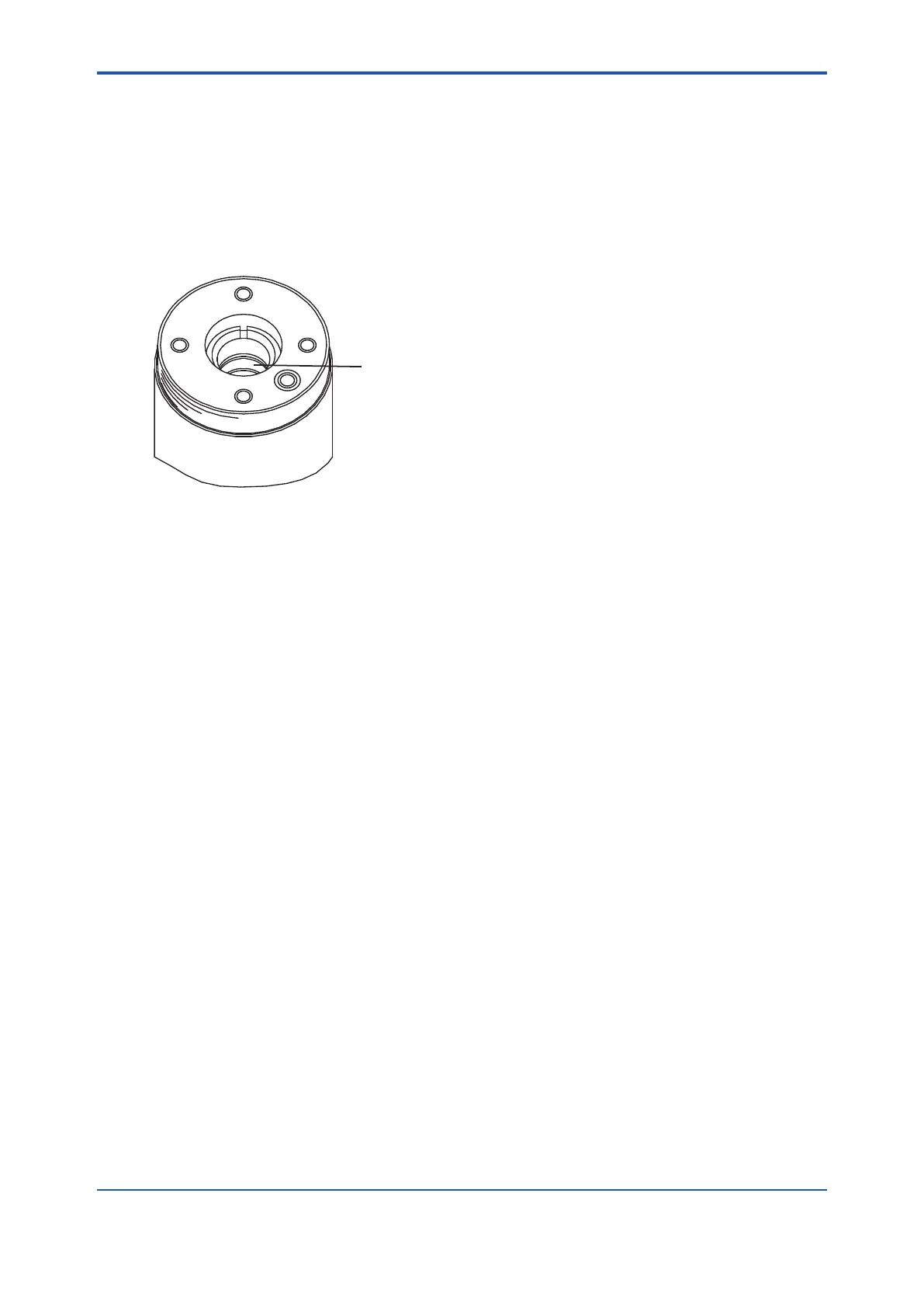
(1) First, install the contact. Being careful not to cause irregularities in the pitch of the coil spirals
(i.e., not to bend the coil out of shape), place it in the ringed groove properly so that it forms
a solid contact.
Groove in which the contact
(E7042BS) is placed
F11.2E.ai
Figure 11.2 Installing the Contact
(2) Next, make sure that the O-ring groove on the ange surface of the sensor (cell) is clean.
Install the metal O-ring in that O-ring groove, and then insert the sensor (cell) in the probe
while turning it clockwise. After inserting it until the metal O-ring comes in contact with the
probe’s O-ring contact surface, properly align the U-shaped-pipe insertion holes with the bolt
openings.
(3) Attach the U-shaped pipe to its support, then fully insert the U-shaped pipe, lter and its
support into the probe.
(4) Coat the threads of the four bolts with antiseize grease and then screw them in along with
the washers. First, tighten the four bolts uniformly by hand, and then use a torque wrench
to tighten all areas of the metal O-ring uniformly, that is, to make sure the sensor ange is
perfectly horizontal to the O-ring’s working face in the probe. This is done by tightening rst
one bolt and then its opposing bolt each 1/8 turn, and then one of the other bolts followed by
its opposing bolt, each also 1/8 turn.
This continues in rotating fashion until they are all fully tightened with the torque wrench
preset to approximately 5.9 Nm. If they are not uniformly tightened, the sensor or heater
may be damaged. Check with light that there is no gap between sensor ange and probe.
Replacement of the sensor assembly is now complete. Install the detector and restart
operation. Calibrate the instrument before making a measurement.
10th Edition : Aug.14,2015-00

 Loading...


